|
Wheel of FORTUNE |
|
This circuit turn on one LED at a time on the circle of LEDs when the push button is pressed. When it is released, the LEDs slow down and finally stop on your lucky number. Principle of Operation The circuit consists of a 555 IC configured to oscillate and the frequency of oscillation depending on the voltage on the 47u electrolytic. When the button is pressed, the voltage on this capacitor is very close to rail voltage because the push switch charges the 100u on the base of the BC547 transistor and this effectively create a power supply for the timing section of the 555. The transistor is called an emitter-follower and it will deliver current via the emitter, through the 1k to the 47u. As it delivers current, a very small (about 100th) is also taken from the 100u and to speed-up the discharge of the 100u it has a 470k across it. As the 100u discharges, it takes longer for the 47u to charge to 2.3 rail voltage and the output frequency of the 555 gradually decreases. Eventually the voltage supplied by the transistor is not sufficient to keep the 555 oscillating and it "freezes." The circuit stops on your lucky number. The Circuit
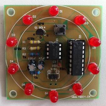
The photo identifies all the components and
how to fit them to the printed circuit board.
You can see the
flat on the side of the LED and the placement of the two electrolytics. The
two 1k resistors are in the centre with the to 470k resistors. You can buy this kit for about $5.00 post-free
21-7-2013 |