|
ç Page 2
è
PIC PROGRAMMING
COURSE
We get a lot of emails from readers wanting to enroll in the PIC Programming
Course. Most of them think the course is $250 - $750 or more!
No. The shock is the course is only
$9.95
for the CD, plus the cost of the kits and postage.
The kits you will need are:
1. Multi Chip Programmer
Buy Kit or
ready-built and tested
2.
PIC LAB-1
Buy Kit or
ready built and tested
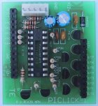
3. PIC Lick-1
Buy Kit
4.
5x7
Display
Buy
Kit
5. Robot Beacon
Buy Kit
6.
8pin to 18pin Adapter
Buy Kit
7.
Tic Tac Toe (introduces PIC16F628)
Buy Kit
If any of the links don't work, send an email to
Talking Electronics
for more details
and how to order everything at once.
The course starts with a simple program such as "Turning on a LED"
and advances to algorithmical routines that solve a problem. It's
the only course that teaches PIC programming. Buy the kits in the order numbered
above and you will be
able to progress through the course.
We also have a number of projects in our "FREE Projects
Section." This section is available to everyone and is intended to show
the range and completeness of the designs we are presenting.
However, the majority of the site is only available by
subscription and the details for subscribing are
HERE.
LATEST
ADDITION
Another piece of the programming jig-saw puzzle has been added
to the site.
Our aim has been to make programming as simple as possible. We
have described the "ins and outs" of the instruction-set for the
PIC16F84A microcontroller chip and produced a complete Library of Routines.
We also have a WordPad version of the routines so you can
"Copy and Paste" them into your own program.
The first thing to do is think of a project that can be developed
using a microcontroller. We have lots of ideas and concepts in the
PIC Microcontroller Course to help you. This is in our subscription
section and you need to
subscribe to see the course.
We have also presented a number of projects and programs in the
Projects section on the left-index and these will show you how they are put together.
You need to do a bit of
homework and study them to see how they
are written.
Once you have an idea of the layout and the capability of a
microcontroller, you can think about developing something
yourself.
Look through "Library of Routines".
It contains nearly every sub-routine you will need.
Then go to "Copy and Paste"
Routines.
These are in WordPad
format. It has a template and is the starting-point for your
program.
Open another WordPad and paste the template.
Delete the instructions you don't want and copy sub-routines as
you need them.
This will produce a .asm file. (Commonly called "your program.")
The file is then assembled by MPASM to produce a .hex file
The .hex file is loaded into IC-Prog v5 and "burnt" into a PIC16F84A
chip.
The result is your own program with the least amount of hassle.
It all sounds so simple and in fact it is. All the steps and stages
are laid out and backed up by projects, theory and kits.
It's the only way to start programming from the
"ground-up." We are constantly getting emails from
readers who have bought the Multi Chip Programmer and they are
saying "finally I am getting somewhere with PIC programming."
See more information in
Discussion-5.
LATEST
PROJECT
In the list above is our
PIC Lick-1 project. The PC board is effectively a
PIC16F84A or PIC16F628 chip with buffered inputs and outputs. It
allows a PIC chip to drive up to 1amp per output. This will allow
you to drive relays, solenoids, motors, globes and other
high-power devices. Go to it after you have read the
PIC LAB-1 project.
|
PIC LICK-1
|
Feedback from a
customer:
A great kit. It is well targeted for the model train hobbyist
and home grown burglar alarm freaks like me.
I used it to design my customized "yellow/alert" alarm system
for my garage and the PIC LAB-1 to debug it.
Mike Skypek |
FM
BUGS
This is a new topic
for the e-magazine, but not a new area to us. It's FM
transmission. The author has been fascinated with the concept of
transmitting an FM signal over a long distance with the least
power. This has led him to develop a wide range of FM
transmitters, commonly called FM BUGS.
Most of the FM transmitter circuits presented in hobby magazines
lack the technical detail to achieve an impressive range.
Either the circuit is too spread-out on the PC board, the coil and
capacitor in the oscillator circuit don't match (don't produce a
"high-Q"), the coil is a
printed track on the board or the supply voltage is incorrect for
the component values.
In this new section, we will be presenting
a number of FM transmitters and will be explaining how they work,
in detail.
The legal power limit for a transmitter varies throughout the world,
ranging from a total ban, to almost any output power, providing you are
in the allotted band. Some countries allow
a few milliwatts while others have no specifications. Some
countries provide an "experimenters license."
Before producing any of these devices, you need to find out the
requirements in your locality.
All the circuits are provided for educational purposes only.
Go now to our
FM
transmitter section and I am sure you will get totally hooked.
MORE!
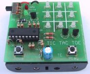
Another one of our projects
is
Tic Tac Toe.
 |
$22.75
plus $5.50
post
 |
It uses a PIC16F628 to drive 9
bi-colored LEDs. The program is so good, you cannot win! It has
"player-first" or "computer-first" feature and a number of effects on the 3x3
display to show how to get the best from the red/orange/green
illuminations.
If you really want to get into programming, this is one project
you shouldn't miss. It introduces ALGORITHMS and shows how to
solve a problem with a routine.
If you want to produce "running letter displays" this project
shows how to produce animations with "cells."
We have added a program to the Tic Tac Toe project. It is
called Duo Dice. It shows how to produce a program for the
3x3 display. All you have to do is make the Tic Tac Toe
project, add the extra routines and you have a completely different project!
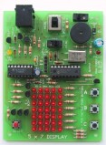
ANOTHER EDUCATIONAL PROJECT
Learn PIC programming with our
5x7 Display:
 |
$46.25
plus $5.50
post
|
It uses a PIC16F84 and CD4017 to drive 35 LEDs. All sorts of
effects can be created on the display including counting up and
down, 2 digit counting, animation effects and lots more. The
project includes over 25 experiments, with each line of code fully
explained.
THE INDUCTOR
Three pages on INDUCTORS have been added to the BEC course
- pages 69, 70 and 71. We have covered this component in an
entirely different way to conventional text-books - using
animations.
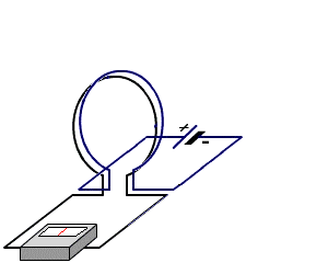
Watch the needle when the coil is moving
away from the detecting loop.
Read the entire article on the subscription section and you
will fully understand how this component works.
THE OP-AMP
Two pages on the OP-AMP have been added to the BEC course.
Animated diagrams show how the op-amp works when a voltage is
applied to the inputs in various configurations, including single
rail and dual rail supplies.
Here is just one of the animations:
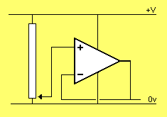
MOUSEOVER
FOR FLY-IN
Go to:
Page 3
|