|
Go to:
Talking Electronics
Build
this . . .
Tests capacitors from 1p
to 10u, in 6 ranges
Connect it to your
multimeter (0v - 10v scale)

This simple add-on capacitance meter has been specially designed to help you
identify capacitors from 1p to 10u.
There has always been a problem identifying capacitors, due to the enormous
variety in size, shape and coding. Most of the time it is impossible to
identify them by size due to the different forms of construction. So
you have to be able to read and interpret the codes on the body. But if the
numbers are missing or microscopic in size, you have a problem. The only
solution is to have a piece of test equipment to identify them for you.
|
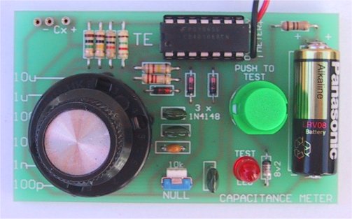
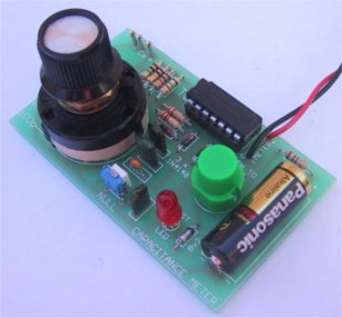
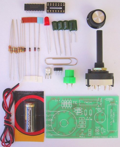
Two views of the Capacitance Meter |
|
Add on CAPACITANCE METER CIRCUIT |
This project is exactly what you need. It is simple to construct and can be
connected to almost any analogue multimeter.
The scales are accurate over each range - certainly good enough to provide you
with the value of any capacitor between 1p and 10u.
The actual accuracy depends on the tolerance of the components used in the
design and since we have used 10% components, you can assume this accuracy for
any of the readings you take. It is interesting to note that the actual value of
a capacitor is not important for most applications.
Coupling capacitors can be +/-50% without affecting performance, as can bypass
capacitors. About the only types that have to be accurate are tuning capacitors
and those in oscillators, and then there is usually a trimmer cap or slug tuned
coil that can be adjusted to set the frequency.
The reason we designed this project was a result of our need to determine the
value of a couple of capacitors we were using in the front end of an RF motion
detector (yet to be released). It had to be 1.8p and the capacitors I found in
our parts store looked like 18p - it was difficult to read the value printed on
the body. I had to borrow one of the staff's capacitor testers to prove it was
1p8.
When you are working with high frequencies such as 400MHz, capacitors have to
be the correct value or the circuit will not work. Certainly an 18p will not
work in place of a 1p8 in an oscillator stage at this frequency.
The tester proved so handy I thought it would be a good idea to present
something similar as a project.
It's very handy when you are not sure of a value. This is especially important
with surface-mount components as their value is not marked on the body and the
size is no indication of capacitance. Many capacitors are made in layers to
reduce their size and this is certainly the case with surface-mount. We have
instances where 10p is physically larger than 22n! - this is because the 22n
is made up of many layers.
Ceramic capacitors can sometimes be a problem too. Their size is also dependent
on the layer principle and a 22n can be the same size as a 10p or even smaller!
There is also a problem with the markings. Sometimes 100p is marked as "100"
and sometimes "101." You have to think every time you pick up a component and
remember the coding being used - if you don't want to make a mistake.
At the end of this article we have included a section on the coding of capacitors and this
will help you identify some of the more difficult values.
If you make a mistake and put 102 or 103 in a circuit in place of 100p, you may
be creating a fault that you will never locate as 102 is 1n and 103 is 10n. We
have also had the case of a 1n capacitor being marked 1n0. The numbers were so
small that the constructor thought it was 100, and used it as a 100p!
It's even more difficult to decipher 5.6p from 56p on tiny ceramic capacitors
as the decimal point is so small that a magnifying glass can hardly pick it up.
Another trap is the marking of capacitors such as 47000 instead of 47n or .0022
instead of 2n2.
When we are making up the kits, we know a component is 5p6 because it comes
from a box labelled 5p6 or marked on the bag as 5p6, but when you pick up some
oddments from a junk box, you can't be quite so certain.
When you are experimenting with high frequency circuits such as RF stages in
transmitters, you will very soon realise the importance of "p" values. The
difference of only a few "p" will change the frequency many MHz, depending on
where it is situated in the circuit. The wrong value will even prevent a stage
from oscillating.
So there we have it, some capacitors are critical and some can be almost any
value.
Going back to the old radio days and the introduction of transistor radios,
some of the ceramic capacitors had a tolerance of 50% to 80%. This wasn't a
problem as they were used in bypass situations and for coupling where a value
could be increased by as much as 100% without any affect in performance.
Tolerance has improved with modern components and the normal tolerance is now
about 10% to 20% but we need not be concerned with the accuracy of a capacitor,
or the tester, but rather the need to determine if the value marked on the body
is the same as it appears to a circuit.
By double-checking with a tester, you will prevent silly mistakes such as using
a 10n capacitor in place of a 1n or 5p6 in place of 56p.
Now to the technical part . . .
Measuring from 1p to 10u is a factor of 10 million. To cover this we need 6
ranges. Each range is divided into 100 parts, making it easy to read values on
a 0-10v scale.
For each range we need to switch some of the components into circuit to create
the necessary test frequencies and charging values. This is the function of the
rotary switch.
All you have to do is fit the unknown capacitor to the test socket and press
the button.
If you don't know the value of the capacitor at all, you can start on any
range. When on an incorrect range, the needle will swing full scale or not move
at all. Only when it’s on the correct range will deflect the appropriate
value.
The only other time when the needle will swing full-scale is when the
value is equal to full scale deflection. This may sound a bit complex but
you'll see what we mean in a moment.
|
Block Diagram of the Capacitance
Meter |
HOW THE CIRCUIT WORKS
This circuit reads the value of a capacitor and displays it on an analogue
meter.
Designing a circuit to do this is considerably more difficult than you think as
the only way to read a capacitor is to charge it and measure how long it takes
to charge.
As you may be aware, the charging of a capacitor is a non linear function and
so we must create a circuit that by-passes the non linear problems and works on
a linear arrangement.
We have done this by charging the capacitor to a specified voltage level and
this level is detected by a gate.
|
The input of the 74c14 detects the
voltage on the capacitor at 70% and up to this point the charging is quite linear.
|
We wanted to use our favourite chip, the 74c14 hex Schmitt Trigger in this
project. It operates by detecting 2/3 of the rail voltage to change the state
of the output. At first it seemed that this could not be used to create a
linear output. But where there's a will, there's a way.
Not only does the
circuit produce very good linearity, but it is simpler and better than anything
else we have seen.
The circuit works on a timing principle. The first
oscillator, between pins 1 and 2 has a high time of 100 units and a low of 1
unit.
The HIGH is created by the 120k resistor and the capacitor selected by the
rotary switch and the low is created by the 2k2 and diode.
This gives us our starting point where we can divide a scale into 100 parts.
The next section of the circuit charges the test capacitor via a resistor
selected by the rotary switch.
The requirement of this section is to charge the largest capacitor (in the
range) in exactly 100 units of time.
This means a 100p capacitor will take 100 units of time to charge and it will
not quite get to the point where the gate detects a HIGH before the output of
the timing oscillator goes tow and discharges it, ready for the next cycle.
This means the output pin 4 will not go low so that the 3n3 capacitor will
remain fully charged.
The third gate inverts this result so that output pin 6 remains low and thus
the meter gives a full range reading of 10v. This is read as "100" to give a
value of 100p.
If a 99p capacitor is tested, it will charge in 99 units of time and the output
pin 4 of the Schmitt gate will go low for one unit of time and discharge the
3n3 capacitor. This will make output pin 6 of the third Schmitt trigger HIGH
for one unit of time and thus the meter will be turned off for one unit of time
out of 100.
Now, here comes the clever part.
Since the circuit is operating at a fairly high frequency, the needle of the
meter does not have time to swing back to zero during this one unit of time but
it does drop a small amount and the result is it sits on 9.9, or "99" on the
scale.
At the other end of the scale, if a 1p is fitted, the capacitor will charge in
one unit of time and output pin 4 will go low for 99 units of time. The
inverter between pins 5 and 6 will produce a one-unit pulse to the meter and
thus the needle will rise .1 v and this will be read as "1" or 1p.
Now we come to the nulling circuit made up of the 10k pot and 3n3.
If no capacitor is fitted to the test terminals, the mark-space ratio
oscillator will produce a high for 100 parts, and a low for one part of the
time and this will go directly through the inverter between pins 3 and 4.
If the nulling components were not present, output pin 6 would be high for 100
parts and low for one part.
This means it would put a small "set" of about one part on the meter and cause a
unit deflection. In other words the meter would not zero and when measuring the
low values in any of the ranges, such as 1p, 1n etc, the needle would add one
to the result to get "2" etc. This may not be important at 100p, but at 2p2 the
value will be 3p3 and it would be annoying to have to take 1p off the readings.
Another solution is to re-zero the meter but the best solution is to provide a nulling circuit.
The 3n3 and 10k trim pot are designed to create a timing circuit that takes one
unit of time to charge and thus the first one unit of time is not registered on
the output.
The other features of the circuit are a voltage stabilised section made up of a
zener diode and 100R resistor as well as a LED to indicate the battery voltage
is above the 10v required to drive the circuit and a test button so that power
is only applied for the brief moment when you want to make a test.
A 12v lighter battery has very little capacity and cannot be expected to supply
a circuit for any more than a few moments at a time.
|
The Add-on Capacitance Meter
kit |
|
PARTS LIST |
1 - 100R
1 - 1k5
1 - 2k2
1 - 10k
1 - 100k
1 - 120k
1 - 1M
1 - 10k mini trim pot
1 - 1n greencap (102)
1 - 3n3 greencap (332)
1 - 10n greencap (103)
1 - 100n monoblock (104)
3 - 1N4148 diodes
1 - 8v2 zener
1 - 5mm red LED
1 - 74c14 Hex Schmitt trigger IC
1 - 14 pin IC socket
1 - 2 pole 6 position rotary switch
1 - knob to suit
1 - push button
1 - 12v lighter battery
3 - machine pins for test socket
1 - 20cm red hook-up flex
1 - 20cm black hook-up flex
2 - paper clips for multimeter
1 - CAPACITANCE METER PC BOARD |
|
Extras: |
| You will also need a 0v - 10v meter. |
|
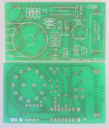
Capacitance Meter Printed
Circuit Board |
CONSTRUCTION
All the components fit on a compact PC board with the 12v lighter battery
soldered on the board too.
The range switch is a PC mount type so that no wires are needed between the
switch and board. This makes the project very neat and tidy
The first item to fit is the IC socket, making sure the cut-out at the end of
the socket goes over the mark on the PC board. This will help you fit the chip
around the correct way at the completion of construction.
Next fit the small components such as the resistors, diodes, capacitors and
zener, along with the LED, slide-switch and trim pot.
The machine pins for the test capacitor are from an IC socket and these are
added to the board to complete the small components. All that's left is the
fitting of the rotary switch and the tinned copper wire for the 12v lighter
battery.
It is not easy to see how the battery is held in position by viewing the
photos. Put a loop
of tinned copper wire into two holes on the PC board and solder it in position.
Do the same at the other end of where the battery will be fitted. Place the battery in position and solder the positive end of the battery to the
loop of tinned copper wire and the negative end of the battery to the other
loop of wire.
You must be fairly quick to prevent the battery heating up.
Solder red and black leads to the 2 paper clips and solder the leads to the PC
board. Bend the paper clips to fit the + & - sockets of the multimeter. Fit the
knob to the switch and add the IC to the socket to complete construction.
Press the push switch and see the LED come on. It should now be ready for
setting up and testing.
THE NULL CIRCUIT
Before the Capacitance Meter can be used for the first time, the output must be
nulled so that it produces a zero reading when no capacitor is fined.
To do this, connect the paper clips to a multimeter set to 10 volts and press
the button. Turn the 10k mini trim pot until the needle just reaches the zero
mark. It is now ready for use.
|
The 6 ranges for the Capacitance
Meter.
The 0 - 10 on the scale can be divided
into 10 parts: 1p, 2p, 3p etc. |
USING THE CAPACITANCE METER
The capacitance meter is very simple to use. Simply connect the two leads to a
multimeter and insert a capacitor in the test pins.
The 10v scale is divided into 100 parts and this makes it easy to read the 1p
to 100p range. The other ranges need a little bit of assistance and we have
provided a diagram above to help you read each of the scales. Some of the
scales overlap slightly and it is always best to get a reading on the largest
scale.
IF IT DOESN'T WORK
There's nothing worse than a piece of test equipment failing to work or being
inaccurate. After all, we use it at the most desperate of times and it has to
be reliable.
That’s why we have made this project compact, with its own supply. Simply by
pressing the button you can see if the battery has sufficient voltage to power
the project.
But if it fails to work after construction, here is the process to follow:
First press the button and make sure the LED comes on.
If it doesn't, measure the voltage of the battery and the track-work around the
switch and 100R resistor for shorts or broken tracks. Measure the voltage
before the 100R and after it. If it is 12v after the resistor, the LED or zener
is faulty or around the wrong way. The voltage on the chip should be very close
to 10v.
The next step is to short between the two terminals of the test socket. This
will cause full deflection of the meter. If this does not happen, the fault
will lie in the second and third inverters or the meter. If the LED goes out
when you short the terminals on the 10u scale, the battery will be getting very
weak.
If it goes out on any of the other scales, the fault will lie in the value of
the charging resistors on pin 3 or the placement of the diode on pin 3.
You must get full scale deflection of the meter, or at least near full scale
deflection before proceeding further.
To check the inverter between pins 3 and 4, short the test pins with a jumper
lead and place another jumper between pin 5 and the positive rail.
This should provide full scale reading, but if it doesn't, place a third jumper
between pin 6 and the negative rail.
This has to work as we are placing the meter directly across the power rails
and if it is not deflecting, the leads are faulty or the multimeter is on the
wrong scale.
We can now start to work backwards, firstly removing the jumper on
pin 6. Each time you take a measurement, press the button for only a second so
that you don't use up too much of the battery.
Output pin 6 should be low, but if it is not, the inverter may be damaged or
the chip may not be getting its voltage from the supply.
A damaged inverter can be replaced by one of the other 3 inverters in the chip
and this simply means wiring up one of them to the meter.
Now remove the jumper on pin 5 and place it on pin 4. Turn the pot to minimum
resistance and the meter should provide full scale deflection. If it doesn't,
the mini trim pot is faulty.
Remove the jumper on pin 4 and we are back to
where we started.
If the meter doesn't give a reading, the inverter between
pins 3 and 4 will be faulty and can be replaced with one of the spare inverters
in the chip.
We have now checked about half the circuit.
The only section
remaining is the mark-space ratio oscillator. This is designed to produce a
very short low and a long HIGH. When the output is HIGH the diode between pins
2 and 4 does not have any effect of the second section where the test capacitor
is charging.
However when the output goes LOW, the diode discharges the test
capacitor.
This section is very difficult to test as it is operating at a high
frequency and is classified as a high impedance stage.
This means you cannot
put any load on the components otherwise the circuit will stop operating.
The only thing you can do is connect a LED from the bottom of the 1k5 resistor to
pin 3 of the chip and change the range switch from 100p to 1n or 10n and note
the very slight glow from the LED. It is responding to the 1% of the time when
the output is low. If the LED is bright, there will be a short or leak from pin
3 to the earth rail.
This could be a short under the board or the fact that the
mark-space ratio oscillator is operating on a 50% duty cycle.
This could be due to the absence of the diode in series with the 2k2 resistor.
If the 1n capacitor is shorted with a jumper lead when the range switch is on
the low capacitor range, the LED will go out.
This is the best we can do with simple equipment to show the oscillator is
working. Further tests can be made with a CRO (Cathode-Ray Oscilloscope) or audio amplifier to see or hear
the effects of the oscillator.
CONCLUSION
The Capacitance Meter can be used as-is or fitted into a small jiffy box and
added to your other test equipment.
I am sure you will find it handy for those times when you need to know a value
of capacitance.
|
CAPACITOR CODES |
|
Identifying capacitors has always
been a problem, mainly due to the wide
variety of shapes and sizes on which the numbers must be printed.
But very soon this should be at an end.
A universal 3-digit code has been developed to cover the entire range
from .1p to 1 Farad and this code is very easy to follow.
The main reason why a compact code is needed is due to the size of some
capacitors - such as monoblocks (monolithic), ceramics and chips - they
are very small. There is not enough room for more than three digits and
this is why the code is so good.
In the past, capacitors have been marked in a variety of ways and have
included the disastrous decimal point and sometimes lots of zeros. If you
have ever tried to decide if a mark on a capacitor is a decimal point or
a spot of dirt, you know what I mean. It is absurd to use a decimal point
in such a vital place.
The 3-digit code does away with the decimal point and uses either a
number or letter instead. There are two forms of the 3-digit code. One
uses three digits and the other uses two digits and a letter. An example
of this is a 5p6 capacitor or 10p or 47p.
You will see how the first type is written by reading through the table
below, they are all "p" (puff) values.
At the moment only about half the manufacturers are using this code and a
couple of conflicts exist. Take for instance a 100p ceramic. It can be
marked "100," or “101” whereas "100" on a chip capacitor is
10p. So be
careful.
If you are working with some of the older style equipment, you will find
values such as .0022 or 2200 on mica capacitors and 4700 or 47000 on
polyester capacitors, making it a logistic nightmare to work out the
actual value. All our circuit diagrams and discussions use the easy to
understand code and it corresponds to the coding on the latest
micro-components.
If you want to know where to start when memorising the table, start with
102 = 1n, 103 = 10n and 104 = 100n. All the other values fit into these
three ranges, (or a higher or lower range).
The most essential thing is to put a capacitor into the correct range.
For instance, 222 must be put into the "n" range and then you say
it's "2n2.'”
We don't have trouble with capacitor codes because we take them from
large bins that have clear identification. But when it comes to a bundle
of capacitors in a kit, I know the problems many constructors will be
having. We have them ringing all the time!
If you are having trouble reading capacitor values,
build the CAPACITANCE METER project. That's why we designed it.
| VALUE: |
VALUE WRITTEN ON
THE COMPONENT: |
0.1p
0.22p
0.47p
1.0p
2.2p
4.7p
5.6p
8.2p
10p
22p
47p
56p
100p
220p
470p
560p
820p
1,000p (1n)
2200p (2n2)
4700p (4n7)
8200p (8n2)
10n
22n
47n
100n
220n
470n
1u
2.2u
4.7u
10u
22u
47u
100u
220u
470u
1,000u |
0p1
0p22
0p47
1p0
2p2
4p7
5p6
8p2
10 or 10p, 100 on chip caps
22 or 22p, 220 on chip caps
47 or 47p, 470 on chip caps
56 or 56p, 560 on chip caps
100 on 101, 101 on chip cap
220 or 221, 221 on chip cap
470 or 471, 471 on chip cap
560 or 561, 561 on chip cap
820 or 821, 821 on chip cap
102 on ceramic and chip cap
222 " "
" "
"
472 " "
" "
"
822 " "
" "
"
103 " "
" "
"
223 " "
" "
"
473 " "
" "
"
104 " "
" "
"
224 " "
" "
"
474 " "
" "
"
105 " "
" "
"
These elelctros
usually have
their value marked
in u (on the body), and are
quite easy to identify.
100,000u and higher! |
Finally, mF values
Some magazines use millifarads for the value of large capacitors such as
electrolytics. I don't like to use millifarad values because no
capacitors are marked in millifarads and it only confuses the issue.
1mF = 1,000u. If you saw 1mF in a circuit you may confuse it with 1u.
Similarly 100mF is equal to 100,000u and a mistake could easily be
made. Stick to u, (microfarads) even when it comes to a 100,000u
electrolytic. This way you can't make a mistake. |

|