|
COMBO - 2 |
Click HERE for Hfe article
The major advantage with this design is its automatic operation. All you have to do is fit the three leads of a transistor to the tester in any order and the LEDs will let you know the base and if the transistor is NPN or PNP. Section 3 will identify the collector and emitter leads and provide an indication of the gain of the transistor. So, you have complete identification and the ability to match two devices, if needed.
|
FEATURES: |
| • Tests transistors - locates base lead and
finds CE or BE shorts. • Determines transistor gain • Outputs a signal for testing audio circuits OPERATION: Use section 1 to detect the base lead and determine PNP or NPN. Go to section 2 to determine open or shorted collector-emitter or base-emitter junction. Go to section 3 to determine collector and emitter leads and gain of transistor |
|
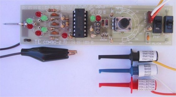
Top view of the Combo-2. The
labels on the EZY clips help with |
|
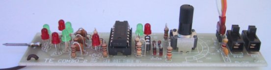
The side view of the Combo-2
showing the components |
|
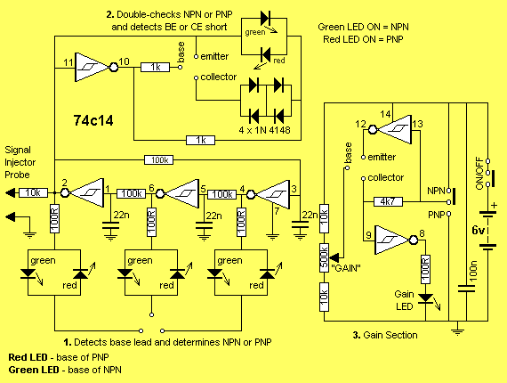
The Combo-2 Circuit Diagram |
The first thing you do is fit the transistor to the 3 hollow pins on the left-hand end of the board, with the leads in any order. The circuit for this section is shown by number 1 on the circuit diagram above.
(If the transistor is too big to connect to the three hollow pins, you can use section 2, where the connections are available via ezy clips on leads).
The base of the transistor will be indicated by a single illuminated LED out of a pair. In other words, five of the 6 LEDs will be illuminated.
If the single-LED is green, the transistor is NPN. If it is red, the transistor is PNP.
This saves swapping the leads until the base is determined. Many of the other testers do not pre-identify any of the leads and its very frustrating if you don't know the pin-out of a transistor.
Next, go to the three hollow pins in the centre of the board and fit the mini plug with the three ezy clips (on leads). This is called section 2 and the polarity of the transistor is further proven and a check is made to see if it has a collector-emitter short or base-emitter short.
All you have to do is fit the transistor so that the base goes to the correct ezy clip and the two LEDs at section 2 will indicate if the transistor has a short in one or more of the junctions or if any are open circuit.
At the moment you don't know the collector from the emitter lead, but this will be determined in Section 3.
The transistor can then be taken to section 3 where the gain is determined. The PNP/NPN switch is set, since you already know this fact from the previous sections.
Turn the gain knob fully clockwise then anticlockwise. If the red LED illuminates or goes out at a low gain value, the collector and emitter leads must be swapped.
You now know the pin-out for the transistor and are ready to determine the gain.
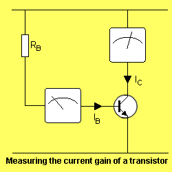
The gain is given the parameter Hfe. This is a value determined by measuring the base current and comparing it to the collector current.
Our tester does not provide an extremely accurate measurement as the scale is very compressed at one end but it does provide a good indication that the transistor is amplifying or if it has a low gain due to a fault.
The gain pot is rotated until the LED just goes out for a PNP transistor. The value is read from the scale around the pot.
For an NPN transistor, the reading is made when the LED just illuminates.
HOW THE CIRCUIT WORKS
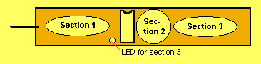
The Combo-2 consists of three sections.
Section 1 is a run-of-three oscillator.
Section 2 is a phase inverter and,
Section 3 is a current gain section.
1. BASE DETECTOR
The run-of-three oscillator consists of three Schmitt inverters connected in a ring with 100k and 22n components in the timing circuit.
When the project is first turned on, the three 22n capacitors are not charged and the input to each inverter is LOW. This makes the outputs HIGH and causes the three 22n's to charge up at the same time via the three 100k resistors.
A race will occur and the first to charge to about 70% of rail voltage will make the input of its Schmitt trigger HIGH. The output of the trigger will go LOW and the 22n on the following gate will begin to discharge via the 100k.
This LOW will cause the output of the second Schmitt trigger to be HIGH and apart from charging the next 22n capacitor, it feeds into a red and green LED via a 100R resistor. We will talk about these LEDs in a moment.
When the second gate charges the 22n to 70% of rail voltage, the gate changes state and its output goes LOW.
This LOW is transferred around to the first gate where it begins to discharge the first 22n in the discussion.
The circuit runs around with one output high, then two outputs high. When an output is HIGH, a green LED is illuminated via a 100R and the current passes through a junction of a transistor placed in the set of three hollow pins. If the junction is forward biased, the current will flow through the junction and through a red LED and 100R to the negative rail. Both the green and red LEDs will turn on.
The way the circuit works is to automatically produce a voltage at every pin in turn and have each of the other two pins at zero. It then produces a voltage at TWO PINS in turn and a low at the third.
This provides all the 6 possibilities for testing the leads of a transistor and because the circuit runs around so fast, there is only one junction that will not conduct. This is the base-collector junction. You have to remember that this method of testing a transistor is not the same as testing it with a multimeter as we are "actively testing it" by suppling the base with a turn-on voltage and causing the collector-emitter junction to conduct.
2. THE COLLECTOR - EMITTER SECTION
This section detects shorts or open junctions between the collector-emitter leads as well as double-checking the NPN or PNP polarity of the transistor.
When an NPN transistor is fitted, only the green LED will illuminate.
The circuit is being fed a voltage that is constantly changing polarity. When output pin 10 of the inverter is HIGH, the NPN transistor is biased ON and the voltage drop across the two lower signal diodes (1.2v) as well as the voltage across the collector-emitter junction (.3v) is too low to allow the red LED to turn ON. The green LED is presently reverse biased and does not turn on.
When the output of the Schmitt trigger goes low, the transistor is reverse biased and the green LED will illuminate.
If a PNP device is fitted, the opposite occurs and the red LED illuminates.
If a faulty device is connected, both LEDs will illuminate if the device has an open collector-emitter junction as the transistor will not be turned on during the forward part of the cycle.
If the device has a short between collector and emitter, neither LED will illuminate as only the forward voltage drop of the two diodes (1.3v) will be present and this is not enough to turn on either LED. (You need at least 1.7v).
3. THE GAIN SECTION
The gain section uses the circuit shown below. Click HERE to see the Hfe article.
When this exact current flows, the voltage across the load resistor is detected by the Schmitt gate and the LED is illuminated (or extinguished) according to the polarity of the transistor.
A slide switch allows the circuit to test both PNP and NPN transistors.
|
Combo-2 kit |
|
PARTS LIST |
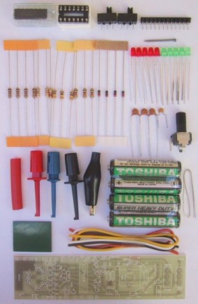
| 4 - 100R 2 - 1k 1 - 4k7 3 - 10k 3 - 100k 1 - 500k mini trim pot with shaft 3 - 22n ceramic 1 - 100n mono-block 4 - 1N4148diodes 5 - 3mm red LEDs 4 - 3mm green LEDs 1 - 74c14 Hex Schmitt trigger IC 1 - 14 pin IC socket 2 - SPDT slide switches 4 - 15cm hook-up flex 1 - Black alligator clip 3 - Coloured EZY clips 11 - Machine pins on strip & 1 pin 1 - 2cm heat-shrink to fit over socket 1 - nail for probe 4 - AAA cells & 2cm double sided tape 1 - 10cm tinned copper wire 1 - COMBO-2 PC BOARD |
|
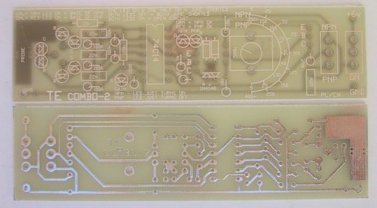
Combo-2 PCB |
CONSTRUCTION
All the components fit on a PC board 107mm x 28mm. Refer to the photos above to see how the machine pins are used as a 3-pin plug for the test leads
so that they can be moved from section 2 to section 3.
|
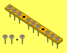
The 4th and 8th hollow pins are removed from the strip and used as sperate pins at the front-end of the board. The strip is then cut into 3 sections of 3 pins and the ends neatly filed. |
PREPARING THE 3-PIN PLUG AND TWO 3-PIN SOCKETS
Supplied in the kit is a strip of 11 machine pins to make the plug and
sockets for the test leads.
From this strip three 3-pin sections are made and two individual pins are
removed (plus 1 pin) for the test pins for section 1.
Remove pins 4 and 8 from the strip and cut it into three pieces making
three 3-pin sections.
Two of these sections are soldered to the board as 3-pin sockets and the
other is turned into a 3-pin plug for the three test leads.
Cut three pieces of hook-up wire to equal length and solder them to the
top of the three machine pins.
Place heat-shrink over both the leads and plug and shrink into place.
Solder 3 Ezy clips to the other ends of the leads and label them
collector, base and emitter with an adhesive label wrapped around the clip.
Mark one end of the 3-pin plug so that it can be fitted the correct way
into the socket on the board.
Start assembling the board by fitting the IC socket and the two 3-pin
sockets.
Then start at one end and fit each component as you come to it.
Each LED is identified on the board with a diode symbol and the cathode
lead is the line on the symbol.
The cathode of the LED is identified by a flat on the side of the body of
the LED and it is also the shorter of the two leads.
The 3 individual machine pins at the end of the board are the next to be
fitted.
These are designed to take the leads of the transistor under test.
The rest of the components are easy to fit as everything is identified on
the board.
The earth lead for the signal injector is soldered to the board at the
point marked GND and an alligator clip is fitted to the other end.
The probe is made from a nail soldered to the underside of the board at
the position marked "probe."
Solder the 4 AAA cells together with short pieces of tinned copper wire.
Don't forget to mark the ON/OFF switch with red nail polish to identify
the ON position.
Fit the IC to the socket so that pin 1 is towards the top of the board
and the project is ready for testing.
|
Section 1 finds BASE lead: |
|
NPN |
only green LED of pair comes on |
|
PNP |
Only red LED of pair comes on |
|
Section 2 double-checks for PNP |
|
Both LEDs off, both junctions shorted |
|
Both LEDs on - open circuit |
|
Green LED ON - NPN, ok |
|
Red LED ON - PNP, ok |
|
Section 3 determines gain: |
|
NPN |
LED just turns on |
|
PNP |
LED just turns off |
TESTING THE CIRCUIT
To test the Combo-2 you will need a number of good transistors, preferably both PNP and NPN types.
Place them in the first section and make sure that only the green LED comes on for the NPN type next to the base lead. Swap the leads around to check that all the LEDs work. Repeat with one or more PNP types.
|
The three Combo-2 sections |
USING THE COMBO-2
When the Combo-2 is turned on, only the two LEDs in Section 2 will come ON. This indicates power is applied to the circuit.
Place the leads of the TRANSISTOR UNDER TEST (sometimes called TUT) in the three machine pins at section 1. If the transistor is "good", five LEDs will come on. The base lead is identified by only one LED of the pair coming on.
If this LED is green, the transistor is NPN. If this LED is red, the transistor is PNP.
Sometimes, if the transistor has shorts between some of its leads, 5 LEDs will come on and so we need section 2 to determine if the transistor is "good."
Connect the transistor to section 2 via the jumper leads and read the LEDs as shown in the table above.
Take the jumper plug to section 3 and determine the gain of the transistor. Turn the gain pot and read the scale from the pointer on the shaft.
THE COMBO-2 AS A SIGNAL INJECTOR
The Combo-2 can be used as a signal injector and is especially handy for locating faults in the front-end of audio projects, such as an FM transmitter.
In the forthcoming issues of this e-magazine we will be presenting a number of FM transmitters and if you get a fault in the audio stages, it is very difficult to locate without some form of test equipment. The only two suitable pieces of test-equipment are: a CRO and a signal injector.
A CRO is the ultimate piece of test gear but is quite expensive. It will provide you with a visual indication of the amplitude and quality of the signal and to get the best results you need to inject the stage with a reference signal. This signal can be either a sine-wave or square-wave and each will provide you with different elements of the whole picture.
The Combo-2 produces a square-wave and has a 10k "safety resistor" on the probe to prevent damaging the circuit being injected or the injector.
The main way to use the injector is to detect the level of signal before and after a particular stage and compare the amplitude -level by listening to the relative sound-level from the a speaker.
With any of the FM transmitters, they should be switched on and transmitting to a nearby radio.
The fault we will be locating is weak (or low) audio. Most of our FM transmitter will detect a pin drop at 1 metre onto a wooden floor, and this is due to the high-sensitivity microphone we use in the kits.
If the microphone has been checked for sensitivity, by fitting it to another identical kit, the fault must lie in the audio amplifier stage.
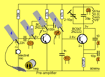
Using the Combo-2 SIGNAL INJECTOR to locate an audio fault
The diagram above shows a typical audio stage with a capacitor input and capacitor output.
The fault could lie in either capacitor being open or shorted and/or a short between any of the components due to a solder-bridge.
Sometimes a voltage-test will pick up the problem but we are assuming all previous tests have not located the fault.
The approach is to start at the "back-end" and work towards the front. This will give a starting amplitude and allow you to hear the frequency of the tone you will be referring to.
This is shown in the diagram as position"1" for the SIGNAL INJECTOR. As you work your way towards the front-end, the signal strength across the capacitor will not vary very much. It may decrease slightly due to the different impedance levels on each side of the capacitor but it will certainly not fall to zero. If no signal is heard at position 2, the fault may lie in the capacitor being open circuit or the transistor being shorted (due to a solder-bridge etc).
The signal-level will be higher when testing position 3 due to the gain of the transistor and if this is not detected, the transistor may be shorted or fitted incorrectly.
The level between positions 3 and 4 will be almost the same and any major difference may be due to the electret mic around the wrong way and thus creating a low-impedance path to ground or a solder-bridge on the PC board.
All audio amplifiers are treated in the same way, starting from the output and working towards the front-end. In this way the speaker becomes your output device and you can hear the relative intensity of the sound.
You can also add an attenuating resistor to the Signal Injector (on either line) to make the intensity of the signal more pronounced after a particular amplifying stage.
The most important point to remember is the intensity. You must be able to detect an increase or decrease in level as you move through a circuit. The actual quality of the tone, such as distortion, is a topic for another discussion.
The signal Injector locates both major and minor faults but without its assistance, an audio fault in the front-end of a project can be an enormous frustration.
CONCLUSION
This project should solve a lot of your problems with identifying transistors, especially odd pin-out varieties. And it is very handy as a Signal Injector for audio-work. Add it to your collection of test equipment and most of all, don't loan it as you will never get it back!