|
Continuity Tester |
ESSENTIAL FOR SERVICING DIGITAL PROJECTS
|
MODIFICATION The following modification is needed for this project: The 100R and 120R resistors must be fitted to the board as follows:  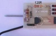 Modification pointed out by: J Patrick |
This is another invaluable piece of test equipment for digital work. It has
been designed by us to cater for a particular application . . . servicing
digital projects sent in for repair.
The first thing you have to do with an unknown project is test the trackwork.
This consists of testing all the tracks for continuity and all the pins for absence
of "shorts."
A
Continuity Tester looks to be a fairly unimportant device and hardly seems
worthwhile constructing, but after you have used it, you will realize how
important it is.
A multimeter can be used but it takes much longer to do the
same job.
Our Continuity Tester has been specially designed and has three very
interesting features.
I'm sure you will add it to your set of test equipment . . .
|
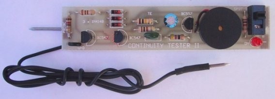
Top view
of the Continuity Tester |
|
CONTINUITY TESTER CIRCUIT |
Our CONTINUITY TESTER gives an audible indication of continuity between the probes so you can keep your eyes on the probe tip. Secondly its response-time is very short so that you can make lots of tests very quickly while listening for the beep.
And thirdly it only responds to a definite short circuit or one that has a resistance of 50 ohms or less. It will not respond to values above 80 ohms or the voltage drop across a diode.
This is where the multimeter falls down. When you are measuring the resistance between pins of a chip on a digital circuit, a protection diode is often present inside the chip and if you measure with a multimeter, it will be difficult to determine if the meter is detecting the presence of a diode or a low resistance.
The Continuity Tester eliminates this problem. We have found it invaluable for diagnosing some of the computers sent in for repair. Most of the problems have been poor soldering but some have been shorts between lands and cracks in the tracks.
To find a short between two pins of say a 24 pin chip, requires 24 x 24 tests and this would take quite a while.
With the Continuity Tester we place the negative lead on the first pin of the chip and quickly wipe the probe down the other pins of the same side then the 12 pins on the other side. The only time you will hear a beep is if a short is present or if the two probes touch.
When you hear a beep, you should examine the track-work carefully to see if a fault is present or if the pins are joined by a track, or some other component.
Continue this procedure with pins 2, 3, 4 etc. until all the possible combinations have been covered.
This is repeated with all the chips in the project and any other connections you can find on the board. This is the only way to locate a hidden short and even though it involves thousands of tests, it will be much quicker than using a multimeter.
HOW THE CIRCUIT WORKS
As we mentioned, the circuit detects resistance values of 50 ohms or less between the probes and allows an oscillator to turn ON and produce a tone from the piezo diaphragm.
A LED is also included on the board to indicate when the unit is ON as the circuit consumes about 2-4mA and the battery would eventually go flat if left on for long periods.
Actually the circuit doesn't detect resistance at all. It detects a threshold voltage across the base-emitter junction of the first transistor. When the tester is in the "rest" state, the first transistor is turned ON and this inhibits the oscillator.
It gets its turn-on voltage from the 100R resistor. The 3v supply is taken through 3 diodes and these drop a total of about 1.9v, leaving about 1.1v for the base bias.
When the transistor is turned on, the base-emitter voltage (the junction-voltage) is .7v and thus .4v is dropped across the 100R resistor. This means we have only .4v leeway for the batteries to fall and when they drop to below 2.6v, the tester will fail to work. That's why we have to conserve energy as much as possible by putting an indicator LED on the board to prevent it being left on.
0.4v across the 100R delivers about 4mA into the base of the gating transistor and this keeps the oscillator OFF. When a resistance of 50R or less is placed between base and emitter, the voltage on the base falls sufficiently to turn the transistor off.
This allows the 2-transistor feedback oscillator to come into operation and produce a tone.
A diode placed between base and emitter of the first transistor will have no effect on the circuit as it will allow .6v to .7v to be appear across the probes and this will not change the state of the circuit. The voltage must drop to .5v or less and this requires a resistance of about 50 ohms or less.
The 2-transistor feedback oscillator is set into operation by the 100k base bias resistor. This turns on the middle transistor and thus its collector voltage falls. The collector is connected to the base of the third transistor and this is also turned on.
The result of this action is to raise the voltage on the collector of the BC 557, to which a 47R is connected. Also connected to the collector is a 10n capacitor and it has presently been charged to about .6v.
As the voltage on the collector rises, it pulls the capacitor up with it and pushes the charge into the base of the middle transistor. This causes the transistor to turn on even harder and very soon we have a situation where both transistors are SATURATED.
The base does not rise above .65v while the other end of the capacitor has been pulled high by the BC 557. This causes it to charge in the opposite direction and after a short period of time its charging current cannot hold the middle transistor ON as hard. The result is the BC 547 turns off slightly and this action is passed to the BC 557 via the 1k & 1u, and the voltage on its collector falls. This action is passed back to the base of the BC 547 via the 10n capacitor and it gets turned off even further.
Both transistors are now completely off and the cycle starts again by the 100k charging the 10n and turning on the BC 547.
The 1k and 1u electrolytic couple the two transistors and the purpose of these has been discussed in the theory sections.
The two leads of the piezo see an AC voltage that is slightly higher than 3v.
Each time the circuit changes state, a click is produced in the piezo and since these clicks are produced in rapid succession, the result is a tone.
|
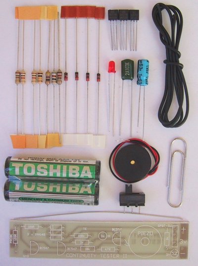
Continuity Tester Kit |
|
PARTS LIST |
|
1 - 82R |
|
1 - 47R 1 - 100R 1 - 120R 2 - 1k 1 - 100k 1 - 10n greencap 1 - 1u 16v PC mount electrolytic 3 - 1N 4148diodes 2 - BC 547 transistors 1 - BC 557 transistor 1 - 3mm red LED 1 - Mini piezo diaphragm 1 - SPDT slide switch 2 - AAA cells 2 - small nails 1 - 10cm tinned copper wire 1 - 50cm hook-up flex 1 - CONTINUITY TESTER PC BOARD |
|
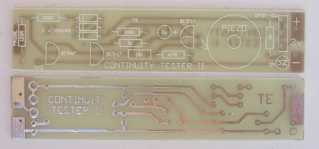
Continuity Tester PCB |
CONSTRUCTING THE TESTER
All the components are mounted on a small PC board that is designed to fit into a toothbrush case. There are a number of suitable cases and even a small one will fit the board. At first we thought the soft type would not be suitable but after we tried it, we found it was the best. The soft plastic is more durable and will not fracture if dropped or bumped. Rigid styrene cases tends to crack very easily and one of ours was crushed under foot when it fell on the floor!
The case is the first item to purchase as it is needed to give you a guide as to the maximum height for the components. If some of the parts are too high, they can be bent over during assembly and its important to know this before you start.
Next you need to make sure the slide switch is the right size for the board. The switch supplied in the kit fits exactly into the holes and any mounting flanges must be cut off so that the board will slide neatly into the case. Make sure you do not take too long to solder it or the operation of the contacts will become faulty due to flux running down the lead. Once this is done, the rest of the components can be fitted.
Start assembly at one end of the board and fit each component as you come to it. The LED, transistors, diodes and electrolytic must be fitted around the correct way and the layout on the board will assist you. If you are not sure, refer to the photos for placement or get someone to assist you, but don’t guess!
The probe tip is made from a small nail and soldered to the underside of the board. The two cells are soldered to the board with short lengths of tinned cop-per wire, provided in the kit.
The wander lead can have either an alligator clip, E-Z clip or nail attached to it.
When everything has been soldered in place, slide the switch ON and the LED will illuminate. Touch the two probes together and the oscillator will emit a tone.
TESTING THE UNIT
You will require a diode, and an 82R resistor.
Place the probes across the diode, firstly in one direction then the other. The tone should not be heard. Place the probes across the 82R resistor and once again the tone should not be emitted. You may find the tester will operate on a resistor which is one value higher or lower than this. The actual value will depend on the battery voltage. But don't worry too much about the actual turn-on and turn-off values as most digital projects have resistors of about 470R in their lines and the tester will not detect them.
IF IT DOESN'T WORK
If the tester does not emit a tone when the two leads are touched together, follow these steps:
Check the voltage of the cells. They should give at least .1v drop across the 100R resistor. If there is no voltage drop, check the voltage-dropping diodes. They should each drop .65v. Also check the supply voltage. It should be higher than 2.6v.
Remove the gating transistor (the first transistor) and turn the unit ON. This will allow the tone circuit to operate. If not, check the value of the 1k and 100k resistors and also their positions. Next check the 10n capacitor and also the BC 547 and BC 557 transistors, they will not work if swapped over or if fitted the wrong way around.
You can determine if the oscillator is jammed in the ON mode or OFF mode by taking a current reading across the switch. If the current is more than 20mA, it is jammed in the ON mode and this means the BC 547 in the oscillator is conducting.
The transistor could be shorted between collector and emitter or the 10n feedback capacitor is open circuit.
Create a short between base and emitter of the BC 547 to bump the circuit into oscillation or replace the 10n.
If the circuit is jammed in the OFF mode, either of the transistors in the oscillator may be open circuit or incorrectly fitted. Try new transistors. If the circuit remains in the OFF state, remove the 10n feedback capacitor and the circuit should turn ON. If it does, the fault will lie in the capacitor being shorted or open circuit.
Once the tone circuit operates, the only other stage to be checked is the gating transistor. If it fails to turn the tone off, the fault will lie in the base bias.
If the gating transistor still fails to turn the tone off, replace it. You may have damaged the base-emitter junction.
This should be sufficient to get the tester working. If not, ask another hobbyist to help you.
HOW TO USE THE TESTER
The project you are going to test must be switched OFF and no part of it should have any voltages present. This is because the input of the tester connects the base of the gating transistor to the probe via a very small value resistor and high voltages (greater than 6v) will destroy the junction by allowing high currents to flow.
Switch the tester ON and the indicator LED will illuminate. Touch the two probes together and the tone will be produced. This is the tone you will be listening for during the tests.
It is important to have a set plan of approach as lots of tests will be required for even the simplest circuit and a logical diagnosis will prevent you going over the same area twice or missing a test.
In the forthcoming issues of POPTRONICS Interactive Edition, we will be presenting a number of projects using a PIC microcontroller. This type of project is one of the reasons why we designed the Continuity Tester.
If the project fails to work, you have quite a number of lines that need checking. All lines need to be checked for continuity and/or shorts and the Continuity Tester will make this task very easy.
We have used it many times for microcontroller projects sent to us for repair. It has found cracks and dry joints the eye missed.
We keep it on the workbench and I am sure you will find it invaluable too.