BASIC 
ELECTRONICS COURSE 
Page 37 INDEX

"Auto-Scoring" Test 

Hello !
This test is designed to see how much you know during the early stages of the course. You can take the test BEFORE starting the course and then after a number of pages to compare the results. 
There are 25 questions and when you have finished, click 
'My Score' button. You will then be given a score plus the correct answers for the questions you got wrong. Start the test now!  It is "Auto-Scoring" and does not have to refer back to the main website for checking.  
All the best,
Colin

1.
What is the colour code for a 47k resistor?
 yellow-purple-red    yellow-green-orange    orange-purple-orange
orange-green-yellow  yellow-purple-yellow    yellow-purple-orange        
2.
What is the value of the following resistor: orange-white-yellow-gold
 3k9 5%    39k 5%    390k 5%    390k  10%   390R  5%                          
3.

Two10k resistors are connected as shown:

What is the combined resistance?

 10k    20k    5k                              
4.

What is the value of this resistor:

 2k2    22k    220k    2M2                            
5.

What is the value of this combination:

 10n    20n    5n                                         
6.

Two resistors are placed in series to:

  Increase the total resistance
  Decrease the total resistance                           

7.

Which set of resistors are found in the standard 5% range:

  22k  39k   47k   55k   68k
  27k  33k   44k   110k   220k   470k
  47k  68k   100k   270k   370k   2M2
  100R  2k2   3k3   4k7   6k6   120k
  22R  33R   47R   68R   100R                                

8.

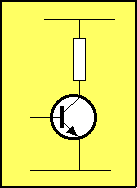
In the diagram on the left, when 
the voltage on the base rises
(i.e: the current into the base
increases) what happens to
the voltage on the collector:

  It rises
  It reduces
  The voltage does not change                                

9.

The transistor-type in question 8 is:

 PNP    NPN    NNP   PNN                           
10.

The input line in question 8 is:

 The Collector    The Base    The Emitter              
11.

From Question 8, we can say:

 The Output is IN-PHASE with the Input  
 The Output is OUT-OF-PHASE with the Input                         
12.

The resistor connected to the collector is called:

 The Bias Resistor   The Dropper Resistor    The Load Resistor                      
13.

Three features of a resistor are:

  Voltage dropping, current dropping, amplifying signals
  Blocking DC, limiting current, biasing
  Current limiting, biasing, voltage dropping
  Blocking AC, Current limiting, amplifying DC signals                      

14.

A Resistor and Capacitor in series is called:

 A Tank Circuit    A Timing Circuit    An Oscillator Circuit             
15.

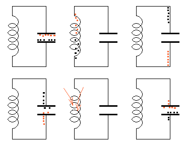
 The animation on the left demonstrates:

 The voltage flowing between a resistor and capacitor
 Energy flowing between a coil and capacitor
 How the Delay circuit works                                                                  
16.

The arrows in the animation in question 15 represent:

 Electrical energy being converted to magnetic flux
 Electricity coming out of the coil
 The direction of flow of current                                       
17.

The natural waveform produced by a Tank Circuit is:

 A Square Wave    A Sine Wave    A Pulse   A Triangular Wave              
18.

The characteristic voltage-drop across a red LED is:

 0.6v    3v    1v7   6v                              
19.

Two 100R resistors in parallel produce a resistance:

 100R    200R    50R                                   
20.

When a transistor "turns-on," the resistance between the collector and emitter terminals:

 Increases    Decreases    Stays the same                      
21.

Two 100n capacitors in parallel produce a capacitance:

 100n    200n    50n                                   
22.

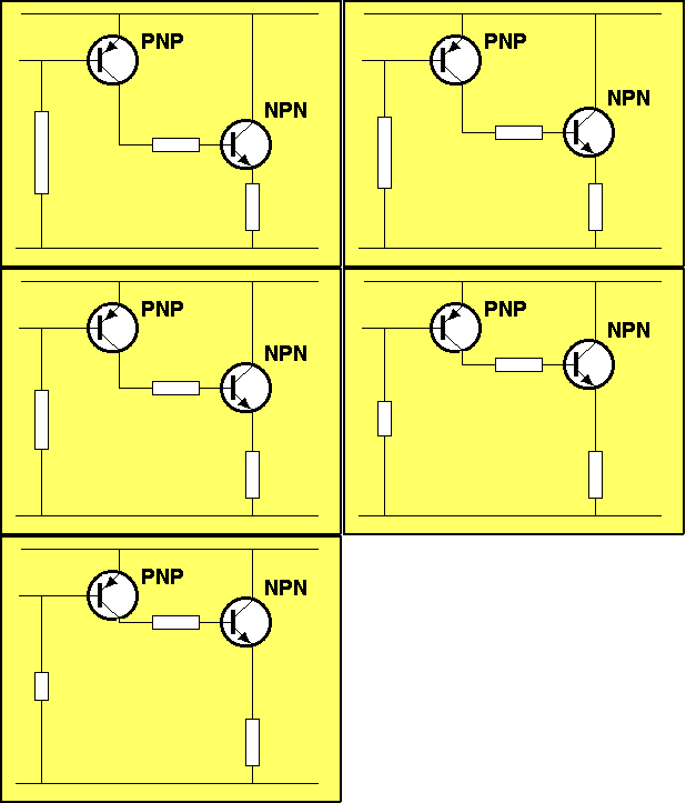
For the animation below, the resistor connected to the input of the first transistor is 
 reducing in value.
This has the effect of:

 Turning ON the PNP transistor   
 Turning OFF the PNP transistor   
 No effect on the circuit                                      

23.

The animation above shows the NPN transistor rising. This is a diagrammatical way of showing the transistor is:

 Delivering more voltage and current to the load   
 Delivering less current to the load   
 The voltage and current to the load remain the same                      
24.

For the animation below, as the voltage on the input rises, the output voltage:

 Falls    Rises    Cannot be determined                       


25.

For the animation above, the input and output voltages are:

 IN PHASE    OUT-OF-PHASE    Cannot be determined              


NEXT