|
|
BASIC
ELECTRONICS COURSE
Page 44  INDEX
INDEX

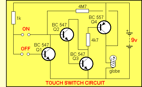
The Touch Switch has a
number of very interesting features. In this section we will discuss them in
detail.
|
 |
Go to previous page to
see the circuit working
 |
|
THE
SUPER-ALPHA PAIR
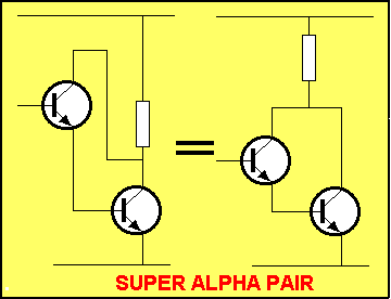
Transistors Q2 and Q3 are connected together in a
very special way. They form a single transistor with a very high gain and very
high input impedance.

The diagrams above show two transistors connected
as a SUPER ALPHA PAIR. The first diagram is taken directly from the TOUCH
SWITCH circuit and the second is re-arranged slightly to show the standard
SUPER ALPHA layout.
You can think of the two transistors as a single transistor. They behave
exactly like a single transistor except the only
difference is the turn-on voltage. It must be 0.6v + 0.6v = 1.2v as the two
base-emitter junctions are "on top of each other."
The other important feature of this arrangement is the high input
impedance.
Normally, the input impedance of a common-emitter transistor is about 2k to 5k.
When two transistors are connected in a super-alpha arrangement, the input
impedance is 200k to 500k.
What does this mean?
The best way to describe this feature is via the time-delay
circuit discussed on page 29. When a capacitor is charging,
current (energy) is being fed to it via a resistor. If we place a monitoring
device across the capacitor, some of the energy from the resistor will flow
into the monitoring device and the capacitor will not charge at the same rate
(It will take longer to charge).
If we need to monitor the voltage across the capacitor (to detect when it
reaches a certain value - to end a time-delay, for example) we need to place a
very light load across the capacitor.
The super-alpha arrangement is ideal for this. It imposes a very light load on
the time-delay circuit. (You will need to place a resistor between the
time-delay circuit and the super-alpha transistor so that the capacitor will
charge above 1.2v (the base-emitter junction voltage of the super-alpha
transistor).
The high input impedance of the super-alpha transistor is needed so that the
circuit will detect a finger across two touch plates.
A finger pressing on two plates presents a resistance to the circuit and will
allow current to flow. Depending on the moisture content and pressure
applied, the resistance can be as low as 30k or as high as 1M. To get reliable
operation, the circuit must be able to detect a high resistance and thus a
very high gain stage is required.
Transistors Q2 and Q3 form a single stage with a gain of at least 100 x 100 =
10,000 and thus an input current of as little as 1uA (1 micro-amp) will allow
a current as high as 10mA to flow in the collector-emitter circuit.
The animation below shows exactly how the super-alpha arrangement works. As
soon as the voltage on the base rises above 1.2v, the "top"
transistor will allow current to flow into the base. The transistor is a
CURRENT AMPLIFIER and it allows about 100 times this current to flow in its
collector-emitter circuit.
At the beginning of the cycle, the lower transistor "sees" the upper
transistor as a very high resistance and it is not turned on.
When the "upper" transistor is turned on, the lower transistor sees
it as a low value resistor (a resistance of about 30k to 100k) and it is
turned ON.
The circuit sees the lower transistor as a very low resistance (about 1k) and
if the supply voltage is 9v, the current flow through the collector-emitter
circuit would be 9mA. But a 4k7 resistor has been included in this circuit to
limit the current less than 2mA.
This current is sufficient to drive the
output transistor into full saturation to turn ON the lamp.
THE OUTPUT STAGE
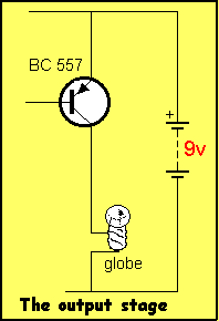
The output transistor is the PNP equivalent of the COMMON EMITTER STAGE. It's
an up-side-down NPN common emitter arrangement.

Once you know how an NPN common emitter arrangement works, the same features
apply to the PNP version. It's essential to have knowledge of these two
"BUILDING BLOCKS" so you can select the appropriate one for
the circuit you are designing.
This is how you decide which circuit to use:
If the voltage into the stage is rising, use an NPN output stage.
If the voltage into the stage is falling, use a PNP output stage.
Referring to the circuit above, when the base if 0.7v below rail voltage, the
transistor turns ON.
A resistor placed between base and 0v rail will make the base voltage 0.7v
lower than rail voltage and the transistor will turn ON.
The current through the base resistor will be multiplied
about 100 times by the transistor and this current will flow in the collector-emitter circuit
(depending on the value of the LOAD. The value of the LOAD can reduce this
value - it cannot increase it above the maximum value specified above).
QUESTIONS
Question 161: Describe the super-alpha pair:

Question 162: What base voltage is required on a super-alpha pair to turn it ON?

Question 163: Name 2 features of the super-alpha pair:

Question 164: If each transistor in a super alpha arrangement has a gain of 70, what is the total gain?

Question 165: Describe the feedback path in the Touch Switch circuit:

Question 166: What is the purpose of the 1k resistor in the Touch Switch circuit?

Question 167: What is the purpose of the 4k7 resistor in the Touch Switch circuit?

Question 168: When the Touch Switch circuit is ON, and the finger is removed, what keeps the circuit ON?

Question 169: When the Touch Switch circuit is ON, how does Q1 turn it OFF?

NEXT

|


