|
BASIC
ELECTRONICS COURSE
Page 46
 INDEX
INDEX

THE
COIL (.
. . continued from previous
page)
The coil can be connected to the
"analogue-to-digital" circuit we covered on
page43.
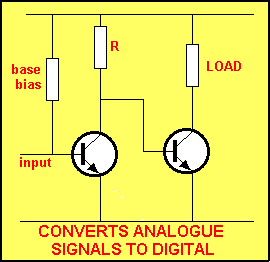 This
requires an input waveform of about 100-300mV to change the state of
the first transistor. The circuit sits with the first transistor
turned ON via the base-bias resistor and if we assume the base is
0.7v, we need to lower the voltage to below 0.55v to turn the
transistor OFF.
The output of the coil needs to be at least 150mV to do this, and providing the
coil can deliver this voltage, the circuit above can be used.
The only way you can decide if the circuit can be employed, is to
connect the coil (the magnetic transducer) and monitor the
results.
The greatest output from a coil is obtained when the coil has the
maximum number of turns and the magnet passes through the centre of
the coil with the greatest velocity.
To double-check the suitability of the circuit, the magnet is passed
through the coil at a slightly slower speed and if it still
operates, the circuit can be used.
It is necessary to place a capacitor between the coil and the input
of the circuit. This is to allow the the
biasing resistor to put 0.7v on the base. If the circuit is connected directly to the coil,
the voltage on the base may be lower than that necessary to turn the
transistor ON (0.55v) (the actual voltage on the base will depend on
the resistance of the coil).
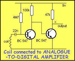
The
output (line X) can be connected directly to a digital gate or
microcontroller input-line.
 to see the circuit above in action.
Remember:
A
North pole entering a coil produces
a voltage of same polarity as a South pole exiting a coil.
Notes:
1: Each graph has a different voltage scale.
2: A magnet must pass a coil quickly so that the pulse
produced will pass
through the 22n capacitor.
3: Note the quick operation of the second transistor - from one
state to the other - this is called "DIGITAL
OPERATION." |
THE
PHOTO
TRANSISTOR
The Photo transistor is an ordinary transistor in a clear plastic
case. Almost any transistor will respond to light and that is why
they have to be in a light-tight case. The silicon material making
up the junction of the transistor changes resistance when it sees
the energy from a light-source and this change is detected between
the collector and emitter leads.
Sometimes as second transistor is also mounted inside the case and
it amplifies the change in resistance to produce a more-sensitive
device. The combination is called a PHOTO-DARLINGTON
TRANSISTOR.
Two less-sensitive devices are also available. They are a
PHOTO-DIODE and PHOTO-RESISTOR (also called a LIGHT-DEPENDENT
RESISTOR - LDR).
Some devices detect visible light while others detect
infra-red.
Getting a photo-detecting circuit to work requires a little bit of
experimentation.
You need to determine if the device is sensitive enough for the
application and then adjust the circuit for the LIGHT and DARK
conditions.
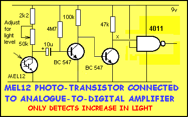
The circuit above can be adjusted so that
almost any light-level can be detected. When light is detected by
the MEL-12 photo-transistor, its resistance DECREASES. This means
the voltage-level sitting on the left-side of the 10u electrolytic
is brought down towards the 0v rail. This causes the right-side of
the electro to fall ALSO. The result is the voltage-level on the
base of the first transistor is REDUCED. This turns the transistor
OFF.
The 50k mini-trim pot
changes the gain of the photo-transistor and makes it more-sensitive
as the resistance of the pot is decreased. The result is the
voltage-fall on the left-side of the 10u electrolytic is greater for
any given change in light and this means a very small change in
light-level will cause the circuit to operate.
The circuit will only detect an increase in light. When the
light-source is removed, the circuit does not respond.
The circuit below is designed to detect when the light-source turns OFF:
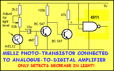
In the following circuit, the A-to-D stage and 4011 NAND gate
have been replaced by a Schmitt Trigger. For details on the
Schmitt Trigger
click HERE.
The MEL-12 Darlington Photo-transistor is connected directly
to the input of the Schmitt gate and the circuit can be adjusted via
the 50k mini-trim pot.
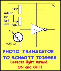
When
the MEL-12 receives light, the voltage on the input of the
Schmitt gate drops from a HIGH value to a LOW value. For the circuit
to work, the LOW value must be 33% of rail voltage or less.
When a light-source is removed from a MEL-12, the voltage on the
input of the Schmitt gate rises to a HIGH value. For the gate to
change state, the voltage must rise to 66% of rail voltage or
higher.
The animation below shows how the mini-trim pot changes the gain of
the photo-transistor.
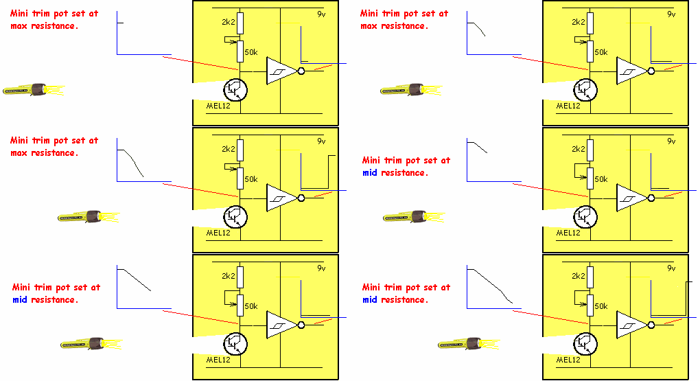
If the change in light intensity is not sufficient to operate the
Schmitt gate, you can add the A-to-D stage described above. You will
need to include the 10u electrolytic for the A-to-D amplifier to
operate.
NEXT

| 


