|
|
BASIC
ELECTRONICS COURSE
Page 47  INDEX
INDEX

Click HERE
for an interactive circuit problem.
THE
MICROPHONE
The output of a microphone is very similar to a high-output
coil. As far as the amplifying circuit is concerned, it sees the microphone
as a sinewave generator (audio is not a perfectly smooth sinewave but a
mixture of many sinewaves occurring at the same time!) This waveform is purposely
over-amplified by the circuit to produce a square-wave. In other words it
produces a waveform with parallel
sides - one that rises and falls very quickly. We have already studied
this on page:18. The process is called "converting an audio waveform to a
digital waveform."
In this type of circuit we are not worrying about distortion. This means we
can concentrate on producing the highest gain from the from the circuit.
Firstly a bit of background on the electret microphone.
The type of microphone we are talking about is actually
classified as a "microphone insert" as a "microphone" is
a hand-held device containing the active "transducer," mounted in a large
case so it can be easily held.
Depending on the level of sound being detected by the microphone, the
circuit will need one or two stages of amplification. It is very difficult
to know if a sound is loud or soft as far as the microphone is concerned and
it's best to design a circuit with extra amplification and a sensitivity
control.
The only way to check the output of a circuit is with a CRO (Cathode Ray
Oscilloscope - see page 9
for a CRO in action) but if you don't have this
piece of equipment, you will need to have extra stage(s) of amplification
and a "sensitivity" control.
THE SENSITIVITY CONTROL
The sensitivity control changes the gain of the microphone and allows it to
produce a higher output (i.e. a higher waveform) for any given audio input. When the
load resistor is reduced, (equal to increasing the sensitivity) the ratio
between the load resistor and the "effective resistance of the
microphone" changes so that more voltage appears across the microphone.
This allows the microphone to produce a higher output waveform.
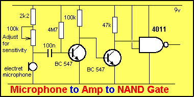
The only problem with the circuit below is the voltage entering the A-to-D
stage must be about 200mV to change the first transistor from its fully
turned-on state (via the 4M7 resistor) to a turned OFF state.
When in a quiescent (stable, steady, resting) state, the voltage on the base
of the first transistor is about 700mV. If a 200mV signal is passed through
the 100n capacitor, the part of the cycle called the "falling
edge" will remove about 200mV from the 700mV and cause the transistor
to turn OFF. This will change the state of the output.
 If
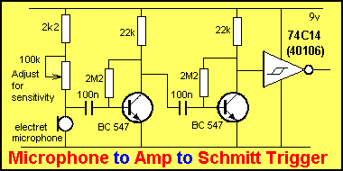
the microphone cannot generate a 200mV signal, the circuit below can
be used. It will amplify signals as low as a few millivolts and pass them to
the input of a Schmitt Trigger. The advantage of a Schmitt Gate is its
ability to accept SLOW-RISING audio waveforms and produce a digital
output.
Click HERE to see the circuit working.
Click HERE to see a question ANSWERED!
The second transistor sits at mid-rail, but this does not upset the Schmitt
Trigger as it only changes when the voltage passes through 70% rail
voltage or 30% rail voltage. When the input sits at mid-rail, the state of
the output will be HIGH if the input has risen from low to mid rail. If the
input has come from rail voltage to mid-rail, the output will be LOW.
The advantage of the Schmitt Trigger is it comes in a set of six gates in a
chip. Each gate can be used in a completely different circuit
and this gives the circuit-designer an enormous variety of circuits that can
be designed around this most-versatile chip. Talking Electronics has
designed quite-complex circuits using just a single Schmitt trigger chip and
a couple of individual transistors.
In the circuit above, you may be able to get away with just a single stage
of amplification, between the microphone and Schmitt Trigger. It will depend
on the intensity of the sound you are detecting.
If you use two stages, you can turn down the sensitivity if only a loud
sound is to be detected.
WATER
PROBES
The circuit for detecting water is exactly the same as for a TOUCH SWITCH. In
technical terms, the probes are detecting a HIGH IMPEDANCE or RESISTANCE. When the probes are not being
touched or are away from water or moisture, the resistance between them will be INFINITY (infinite resistance). When moisture touches them, the
resistance will be between 20k and 200k. The actual resistance will depend on the salts (the salt content) of the water or the sweat in the
finger. (A dry finger will have a resistance higher than 200k and may be
difficult to detect.)
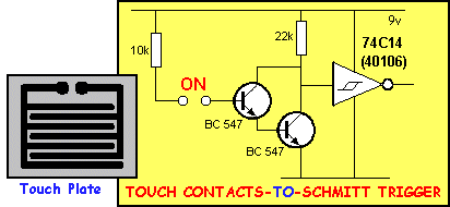
A suitable circuit to detect water is the TOUCH
SWITCH circuit discussed on page 43. The circuit below shows how to
connected the Touch Switch to a Schmitt Trigger. This circuit can now be
connected to an input line of a microcontroller to detect the presence of
water or the input of a TOUCH
PLATE to detect the presence of a finger.
 HOW
THE CIRCUIT WORKS
When the resistance between the
"ON" terminals is reduced, current flows into the base of the
upper transistor. The resistance between the collector-emitter terminals of
the upper transistor reduces and this causes current to flow into the base
of the lower transistor. The lower transistor turns ON and the resistance
between its collector-emitter terminals reduces.
We now have a situation where the circuit is converted into two resistors in
series, with the join going to the input of the Schmitt Trigger. The top
resistor is 22k and the lower resistor is a lower value (say 5k).
These two resistors form a VOLTAGE DIVIDER and the voltage of the 9v supply
appears across each resistor according to its value. The 22k resistor will
have 7.3v across it and the 5k resistor will have 1.6v.
The important point is the percentage of voltage on the input of the Schmitt
Trigger. If it is less than 30% of rail voltage, the Schmitt Trigger will
detect a LOW and the output will be HIGH.
In our example, the output of the circuit will be
HIGH. The 10k resistor in the "touch line" limits the current
into the base to less than 1mA and prevents the transistors being damaged,
if the contacts are shorted.
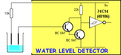
The diagram below shows the circuit connected to water-level probes:
Click HERE to see the circuit working.
HOW THE
CIRCUIT WORKS
When the water touches the tip of the probes, the base voltage on the upper
transistor rises to 1.2v but the current into the combination is very small and
the lower transistor does not turn on. The result is the collector voltage on
the pair is near rail voltage.
As the water rises, the resistance between the probes is reduced and this causes
more current to flow onto the base. The upper transistor starts to turn on and
this turns on the lower transistor. The collector voltage falls.
This action continues until both transistors are fully turned on.
When the collector voltage falls to below 30% of rail voltage, the Schmitt
Trigger changes state and the output goes HIGH.
This action can be seen in the animation by clicking below the Water Level
Detector Circuit above. The level at which
the output changes state will depend on the amount of salt(s) contained in the
water and the size of the electrodes.
PIEZO
DIAPHRAGM
The Piezo Diaphragm is unlike any other transducer (input device). It is a
high impedance device that produces an output voltage when it is deflected.
The deflection may be due to being struck or via sound waves.
Depending on the type of piezo, the output voltage will vary from a few
millivolts to a number of volts.
You cannot determine if a piezo will produce a high or low output without
testing it. Size and shape has not connection with the output voltage. A
piezo will detect audio, just like an electret microphone but it will have a
very "tinny" sound. It sounds like a person talking into an
empty tin. For this reason a piezo cannot be used for quality audio
reception but it can be used to detect when audio (or any type of knock or bang) has
occurred.
The piezo does not have to be supplied with voltage from the power rail and
thus a circuit employing a piezo can designed to consume very little
quiescent current. This makes it ideal for battery operation.
The circuit below shows a typical piezo interface. No capacitor is
needed between the piezo and base of the first transistor as a piezo is
effectively a capacitor of approx 22n.
A piezo consists of a disk of brass or similar material with a thin layer of
ceramic material glued to one side. A very thin layer of conducting
material is then placed over the ceramic material - with the two metal
layers forming the electrodes (electrical connecting points). The result is a capacitor.
When a voltage differential is placed on the two plates, the ceramic
material expands and this causes the brass plate
to "dish."
When the voltage is reversed, the ceramic material contracts and this makes
the plate dish in the opposite direction. If the direction of the voltage is
changed rapidly, the metal plate bends in and out and this creates sound
waves. The sound from these devices is very "harsh or tinny" and
they produce a very high output at a particular frequency called the RESONANT
FREQUENCY. Unfortunately
this frequency is also a very annoying frequency and thus the piezo has a
very bad record for its output.
The piezo also works in reverse. If a soundwave is picked up by the piezo,
the movement of the diaphragm generates a voltage between the two plates and
this can be passed to an amplifying circuit.
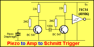
Click HERE to see the circuit
working.
GOING
FURTHER
The circuits we have studied in this section are called INTERFACING
CIRCUITS. They connect an input device to a DIGITAL LINE, such as a
microcontroller.
A Microcontroller requires a signal that is either HIGH or LOW and this is a
very clean signal with a definite outcome.
Once you have a digital signal you can start making decisions and this is
can be done by the program inside the microcontroller.
The program can do a lot of filtering of the signal and make lots of
decisions like operating on the third pulse of a chain of pulses or only a
signal above a certain frequency etc.
Circuits can also be made to have a variable sensitivity by taking an output
line from the microcontroller to control the voltage on the interface
circuit.
In the circuit below we see a glass break detector. The piezo detects the
high pitch of the glass breaking and sends a signal to the PIC12c508A
microcontroller. The microcontroller contains a dialler program that dials a
central monitoring system and gives out an audible Hee-Haw sound as well as
a 6 digit DTMF code to tell the monitoring computer the exact address of the
intrusion. The whole project costs under $30 and is one of the projects
available in our PIC
Microcontroller section.

The
Glass Break Detector circuit is simply a piezo placed on the corner of the glass
being monitored. The circuit is basically very insensitive to sounds as the
noise of glass breaking is considerably louder than all other noises that will
be picked up. The circuit within the micro contains a sound filter that is tuned
to the particular frequency of glass shattering. This prevents false
triggering.
Micro-controllers are amazing devices. A single 8-pin micro-controller can take
the place of 10 or more individual chips such as timers, delays, gates, filters,
and the only circuitry you need to design is the interfacing between the pick-up
device and the input line.
Once you know how to convert a low level (voltage) signal to a digital signal (a 5v signal), you are ready for our microcontroller
section.
NEXT

|


