|
|
BASIC
ELECTRONICS COURSE
Page 48  INDEX
INDEX

REVISION
The previous 3 pages covered INTERFACING between a pick-up device (also known as a
transducer) and a digital line such as the input to a
microcontroller.
Sometimes you can connect a pick-up directly to the input of a
microcontroller. Devices such as switches and some Hall Effect device are examples. The only
requirement is the pick-up must have a voltage swing of at least 80% of rail
voltage. The program in the microcontroller can be designed to remove noise,
switch-bounce, excessive switch-pushing and all types of interference.
Devices that produce a voltage swing less than 80% of voltage rail must have
an INTERFACE CIRCUIT connected between the device and the
microcontroller to bring the voltage up to the required level.
These are the features we have covered in the previous 3 pages.
In this revision test we will go over the design of a number of interface
circuits and make sure you know how they work so you can design these types
of circuits when you go to our microcontroller section.
Question 1:
Draw an interface circuit between an electret microphone and a
microcontroller, consisting of two common-emitter stages. The following
animation will help you with each stage of the design:
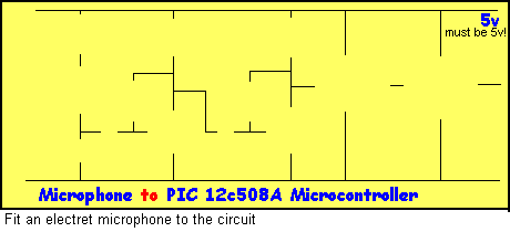
Click and wait for
 file to download
Question 2:
A coil is used to detect the
passing of a magnet. The coil is connected to a common-emitter amplifier and
the output of the transistor is connected to the input line of a
micro-controller.
Draw the circuit and sketch the input to the microcontroller when the magnet
passes the coil.

Click and SLIDE pointer to keep window open
| We have not shown the
output of the micro-controller as it may only change after 15 passes
of the magnet or once every 24 hours! It will depend on the
program. See Question 3 for more details. |
Question 3:
From Question 2, suppose
the PIC microcontroller produces a HIGH when the input is HIGH. Draw
diagrams to show the position of the magnet for the output :
(a) HIGH,
(b) LOW.
Compare your work with the animation below:

Note: the output
of the MICRO can go HIGH for any duration, at ANY time.
It will depend on
the program
you put in it.
Question 4:
Name the pick-up device you would select for the following:
(A number of different pick-up devices can be used for each situation - it will depend on
the exact requirements)
(a) Detecting water level
Answer
(b) Detecting nails in a piece of wood
Answer
See Metal detector Page 24
(c) Customers walking though an open doorway
Answer
(d) Detecting a burglar opening a drawer
Answer
(e) Glass Breakage Detector
Answer
(f) Detecting noises and voices
Answer
(g) Counting cardboard boxes on a conveyor belt
Answer
(h) Detecting the opening of a door
Answer
(i) Detecting walking down a corridor
Answer
(j) Detecting smoke
Answer
(k) Early-Warning Smoke Detector
Answer
|
Question 5:
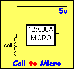
A coil connected to the
input of a microcontroller (as shown in the accompanying diagram)
does not produce sufficient voltage for the micro to detect a HIGH when a magnet passes
over it. Describe 4 ways to improve the circuit.
|
|
Question 6:
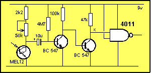
Did you construct the circuit below
on Page 47? If not,
Click HERE.
Question 6(a):
Name the 3 stages in the circuit below:
|
Question 7:
How much of the Metal Detector circuit from Question 4b above, do you
remember? It's important to know what size resistor and/or capacitor goes in
each location. Refresh your memory by constructing the circuit.
Click HERE.
Question 8 :
What is the main fault with each of the following circuits:
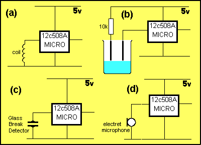
Question
9:
Can you put more
than one "pick-up" device on an input line?
Question
10:
This is a memory
test. Study the circuit then build it by clicking below. You can see how all the features we have covered have been combined to
produce a 4-input dialing alarm. This is one of the projects we will be
covering in the PIC Programming section.
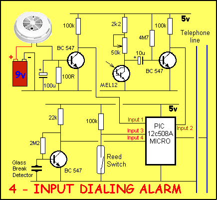
Click HERE to build the circuit.
NEXT

|


