|

The
LASER diode
INDEX
Page 53
This information has been gathered from
a number of sites and recognition
is given to the original
authors. It is very interesting reading and most informative and has been
corrected and improved slightly during the transfer. The only item that needs
discussing is the measurement of current across TP2 in the lower circuit. A
photo-diode does not PRODUCE current or voltage. Read the discussion
below. Otherwise the article(s) are great . . . Colin Mitchell
Note:
780nm is
infrared and 650nm is
visible
(red) output.
Th e
introduction has been provided by:
Samuel M. Goldwasser
E-Mail: sam@stdavids.picker.com
How do I use a visible laser diode?
The quick answer is to be very careful - for two reasons:
(I am assuming a typical 5 mW visible laser diode)
- You can easily destroy the typical laser diode through instantaneous
over-current, static discharge, probing them with a VOM, or just looking at
them the wrong way.
- Anytime you are working with laser light you need to be careful with
respect to the exposure of the beam to your eyes. This is particularly true if you
collimate the beam as it will result in possible instantaneous retinal damage.
Many laser diodes are packaged in a housing that contains an optical sensing
photo diode. This provides a feedback from the laser diode to prevent it from
being over-driven.
The diagrams below show how the laser and photo diode are connected. Laser
diodes are available in visible and non-visible light output. The
non-visible output is called Infrared (IR). On MOST IR diodes
one lead of the laser is connected to the photo diode and tied to the case. The
case is then taken to the NEGATIVE of the supply. On MOST visible laser diodes the case is
POSITIVE!
Typical current for a laser diode is 30-100 mA at 1.7-2.5 V. However, the power
curve is extremely non-linear. There is a lasing threshold below which there
will be no coherent output (though there may be LED type emission). For a diode
rated at a typical current of 85 mA, the threshold current may be 75 mA. This is
one reason why many applications of laser diodes include optical sensing to regulate beam
power. You can easily destroy a laser diode by exceeding the safe current even
for an instant. It is critical to the life of the laser diode that under no
circumstances do you exceed the safe current limit even for a microsecond!
Laser diodes are also extremely static sensitive, so use appropriate
precautions. Also, do not try to test them with a VOM which could on the low
ohms scale supply too much current.
It is possible to drive laser diodes with a DC supply and resistor, but unless
you know the precise value needed, you can easily exceed the ratings.
You can identify the laser diode and the photodiode because the photodiode's
forward voltage drop will be approximately .7v rather than 1.7-2.5v for the laser diode. So, for the test below if you get a forward voltage drop
of under a volt, you are on the photodiode leads. If your voltage goes above 3v, you have the polarity backwards. WARNING: Some laser diodes
have very low reverse voltage ratings and will be destroyed by modest reverse
voltage. Check your spec sheet.
One approach that works for testing is to use a 0-10 VDC supply with a, say
100 ohm resistor in series with the diode, and slowly bring the current up until
you get a beam. However, you still have no idea of when you are at the safe
current limit without an optical power meter.
For an actual application, you should use the optical feedback to regulate
beam power. You should also use a heatsink if you do not already have the laser
diode mounted on one.
The raw beam from a typical laser diode is wedge shaped - 10x30 degrees
typical divergence. You will need a short focal length convex lens to produce
anything approaching a collimated beam.
The circuit below is a constant current regulated power supply for a CW
(Continuous Wave - or Continuously ON) visible laser but it may not apply directly to your configuration of laser
diode and photodiode (polarities may differ). Three terminal regulators can
be used in constant current mode as long as you guarantee there will be no
overshoot, etc. This is really important!
CONSTANT CURRENT SUPPLY FOR LASER
HOW THE CIRCUIT
WORKS
If the photo diode symbol in the diagram above is changed to a photo-cell, the operation of the
circuit will be easier to understand. When the circuit is first turned on, the
voltage across the 10u on the base of the BD139 is zero and the transistor does
not turn on. The BC 328-25 has its emitter fixed a 2.5v and the base is taken to
0v rail via a 10k pot. At the moment the laser diode is not illuminated and thus
the solar cell inside the head is not producing a voltage and the BC 328 is
turned on. This causes the 10u mentioned above to begin to charge.
As the electro charges above 0.65v, the BD 139 begins to turn on. This
illuminates the laser diode and the solar cell begins to generate a voltage. The
output voltage of the solar cell is such that the base voltage of the BC 328
rises and this turns the transistor off. The action of this diode/solar
cell (voltage-producing device) is difficult to understand and so we will
explain it in another way. The device is exactly like a small battery placed on
the 9v rail, with it negative on the rail. This means the positive terminal will
make the 9v rail HIGHER and this voltage is raising the base of the BC 328
transistor. The 10k pot is acting as a voltage divider and so the base of the
BC328 is seeing a voltage that rises when the device in the head of the laser
detects illumination.
The BC 328 is turned off slightly and this turns off the BD139 slightly. The end
result is the laser diode is turned off slightly. This is how the output of the
laser is accurately controlled, even though the voltage of the supply may alter.
CD Player Laser diodes
These are infrared (IR) emitters, usually 780 nm. There is a very
slightly visible red emission. This may be a spurious very low power output in the
red part of the spectrum or your eye's response to the IR appearing red at
about 10,000 times weaker than the actual beam. The main beam is IR and
invisible. Take care. A collimated 5 mW beam is potentially hazardous to your
eyes.
Typical CD laser optics put out about .3-1 mW at the objective lens, though
the diodes themselves may be capable of up to 4 or 5 mW depending on type. If
you saved the optical components, these will be useful in generating a
collimated (focused) beam.
The optics typically consist of a collimating lens, diffraction grating (to
get the three beams in a three beam pickup), polarizer, prism or mirror,
focussing (objective) lens. With the objective lens removed, you should get a
more or less collimated main beam and two weaker side beams. Mix and match
optics for your needs (if you can get it apart non-destructively).
WARNING: A collimated 5 mW bean is hazardous especially since
it is mostly invisible. By the time you realize you have a problem it will be
too late.
The coils around the pickup are used for servo control of focus and tracking
by positioning the lens to within less than a um of optimal based on the return
beam.
Typical currents are in the 30-100 mA range at 1.7-2.5 V. However, the power
curve is extremely non-linear. There is a lasing threshold below which there
will be no output. For a diode rated at a typical current of 40 mA, the
threshold current may be 30 mA. This is one reason why many applications of
laser diodes include optical sensing (a built in photodiode in the same
case as the laser emitter) to regulate beam power. You can easily destroy a
laser diode by exceeding the safe current even for an instant. It is critical to
the life of the laser diode that under no circumstances do you exceed the safe
current limit, even for a microsecond!
Laser diodes are also supposed to be extremely static sensitive, so use
appropriate precautions. Also, do not try to test them with a VOM which could on
the low ohms scale supply too much current.
It is possible to drive laser diodes with a DC supply and resistor, but unless
you know the precise value needed, you can easily exceed the ratings.
You can identify the laser diode and the photodiode because the photodiode's
forward voltage drop will be approximately .7 V rather than 1.7-2.5
V for the laser diode. So, if you get a forward voltage drop
of under a volt, you are on the photodiode leads.
One approach that works for testing is to use a 0-10 VDC supply with a, say
100 ohm resistor in series with the diode, and slowly bring the current up until
you get a beam. Use an IR detector for this! If you get the polarity backwards,
the voltage across the diode will go above 3 volts. This does not seem to damage
the types of diodes found in CD players. Then, turn power off and reverse the
leads. This will not damage either diode.
For an actual application, you should use the optical feedback to regulate the beam power. You should also use a heatsink if you do not already have the laser
diode mounted on one. CD laser diodes are designed for continuous operation.
You can use an LM317 type three terminal regulator in constant current mode as
long as you guarantee that the current never exceeds the set point.
The following has been taken from
Le Magicien website:
KEYCHAIN LASER DRIVER CIRCUIT
This
is a simple description of a cheap
KeyChain Laser that sells for 5 bucks or so.
The basic circuit for powering a laser diode is
as shown below in figure 1.
Most
common Laser Heads have two semiconductors: a LD (laser
diode) and a PD (photodiode).
The laser diode
will be forward biased and its cathode (LDC) will connect
to a driver transistor &/or network to regulate the LD current based on the
photodiode current (feedback network).
The photodiode will be
reverse biased, its anode (PDA) will feed a driver
regulator and thus the control will give a feedback signal for the LD
driver.
The feedback is an optical one with part of the laser beam going backwards to reach the photodiode junction, as shown in figure 2.
As shown in Fig 2, the laser diode head has three leads
labelled:
LDC (Laser Diode Cathode), PDA (Photo Diode Anode) and COM+
(common Positive Terminal).
Inside the laser diode head is the laser
diode itself and a photodiode, used to regulate the laser diode current via an
external feedback loop.
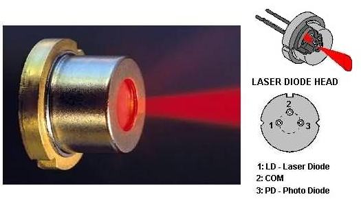
The laser diode head and pin connections.
The schematic for the laser key-chain is shown in fig 4:
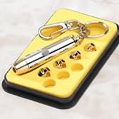
Below is an advert for a 5mW key-chain laser and some visible
laser diode modules from Information
Unlimited. The 1mW key-chain lasers can be found in many "junk-shops" for about $5.00
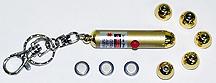 
Patterns may vary from
those shown. mailto:wako2@xtdl.com
- 5 Complex Light Designs
- Fits on Your Key Chain
- 2000 Feet Effective (user) Range
- Includes (3) LR44 Batteries
LAPN65PT
-
5mw 650nm 5 Pattern Laser Pointer...........$12.95
LAPN6542
-
5mw 650nm 42 Pattern Laser Pointer.........$29.95
Visible Laser Diode Modules
3 Volts - High Brightness
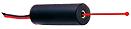
LM630P
- 3mw@630nm 10.5x32mm.................$34.95
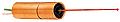 LM650P10
- 10mw@650nm 25x51mm.............$99.95 LM650P10
- 10mw@650nm 25x51mm.............$99.95
 LM650P30
- 30mw@650nm 23x51mm...........$249.95 LM650P30
- 30mw@650nm 23x51mm...........$249.95
LASER DIODE
SUPPLY
A very simple power supply to test a laser diode can be made by connecting a resistor between
the output of an LM317 adjustable regulator and the laser, and taking the common or "adj" terminal as shown
below. The
output current is set by the value of the resistor.
It works like this:
No current "comes out" the adjust terminal. It is a "sense"
line. It merely acts as the 0v reference line for the regulator. The only side
issue is the current taken by the regulator flows through the adjust line and
this is approximately 10mA. But in our discussion, this is ignored.
The voltage between the output terminal and "adjust" is fixed a 1.2v
(for this type of regulator). The 18R resistor in the circuit is called a
voltage dropping resistor. It is designed to produce a voltage across it
according to the current flowing. If it is 18R, the current flow will be: 1.2/18
= 66milliamps. If the resistor is 10R, the current needed to produce 1.2v
across the resistor is: 1.2/10 = 120milliamps. If we choose 15R, the
current flow will be 1.2/15 = 80milliamps.
The laser diode in the example above requires a current between 70milliamps and
100 milliamps. You can choose 15R or 18R for the voltage-dropping resistor. Use
these examples to work out the value of resistor needed for your particular
laser.
Finally,
the following information has been taken from the website of John Yurek, K3PGP@qsl.net
Biasing &
Modulating Laser Diodes
- Safely ! -
After several mishaps trying to set up laser diode feedback regulators I
decided there had to be a better way! The following circuit is a result of my
experimentation. This regulator has been used for CW, MCW, FM, SSB, BPSK and
video with no difficulty. Since going to this circuit I have not lost a single
laser diode! It has been used with laser diodes from 5 mw to 500 mw.
This is a 780nm Infrared set-up. See below for the discussion on TP2.
The circuit allows for 'soft' turn on of the laser diode via the 10 ohm
resistor and 100 uf capacitor on the input of the 7805 regulator. A 1N4007 diode
is provided to prevent reverse bias. The diode was connected across the supply instead
of in series with one line to eliminate the voltage drop associated with a series diode. The 10
ohm resistor will limit the current and prevent any damage under reverse bias
conditions. No fuse is necessary.
Laser diode current is set via R1. Typical values are 39 to 47 ohms for 5 mw
diodes and 22 ohms for 30 mw diodes. To be safe, start out with a
LARGER resistor and work down. It is recommended that you
bring the 12vdc supply up SLOWLY from a variable bench supply
when setting up the circuit while metering TP1 with a voltmeter and noting when
the current reading levels off. (Use a battery operated voltmeter for this as
neither test lead is at ground potential!) After you pass 8 volts or so you will
notice that no matter how much voltage you feed into the circuit the current
will NOT increase. The maximum safe voltage is approx. 35vdc. At NO time
should you allow the current to exceed
Iop as specified by the manufacturer. If
you reach Iop before the circuit limits, increase the value of R1!
NOTE: 1 volt equals
100 ma., meaning that if you are setting up your laser diode for 60ma, the
circuit should be set up so that you read 0.600 volts across TP1 when the
circuit is into full limiting.
If you have the manufactures spec sheet and lm is specified you can measure
this current across TP2. 1 volt equals 1 ma. Some manufacturers return the
photodiode to + 5vdc. See the
discussion below.
The 5.1 volt zener diode hanging across the output of the 7805 voltage
regulator is a safety precaution in case the 7805 should fail. The 5.1 zener
will clamp the voltage to safe level. The 10 ohm input resistor in series with
the 12 volt line will limit the current. This is a also a precaution against any
turn on transients.
The above circuit may appear to be a bit over-designed. However, it seems to
work just fine and since I am presently using this circuit with some laser
diodes that cost as much as $300 a piece I feel safer with the extra protection
provided by this circuit.
The shunt modulator was tried after blowing a couple of diodes with an
experimental series modulator. It was found out too late that if the series
regulator was overdriven it would blow the laser diode even if the 12vdc line
was turned off! I was using an NPN transistor for the series pass transistor and
the overdrive went in the base and came out the emitter which was connected
directly to the laser diode!
The MRF-510 or 511 IgFet (available from Radio Shack) provides very good
linearity when used in this circuit. A 22 ohm resistor in series with the source
lead is used to add a touch of negative feedback. When properly set up the
current as monitored across TP1 will not change very much, if at all, when going
from full power to complete beam cutoff. What is happening is the IgFet is
SHUNTING the current to ground and preventing it from going
into the laser diode. As the IgFet draws more current the laser diode gets less
with the result that the load on the power supply remains fairly constant. The
22 ohm resistor may need slight adjustment for different laser diodes. It
provides a bit of negative feedback and helps to make the modulator more linear.
The circuit above was optimized for a 780 nm 5 mw laser diode.
The modulation input is DC coupled. This means you can apply a
POSITIVE voltage and control the laser power. If your goal is
linear operation such as AM, video, or SSB operation, you should bias this input
for ½ laser power through a series resistor. Apply the AC waveform directly to
the input through a capacitor.
The 1N914 and resistor diode network was added to the IgFet input circuit
after one device developed a gate to drain short causing the drive to be applied
directly to the laser diode!
NOTE: Most laser
diodes typically have one lead of the laser diode and the photodiode tied to the
case. On MOST IR diodes this is the NEGATIVE
terminal. On MOST visible laser diodes the case is
POSITIVE!
If the case is positive on your particular laser diode you will either have
to insulate it from ground or better yet, hook it up as above and change the
7805 to a 7905 (negative 5 volt regulator) and reverse all the capacitors,
diodes, etc… I always feel a LOT safer with the laser diode
body at ground potential!
Several people building this circuit have used the LM317
ADJUSTABLE voltage regulator as a replacement for the fixed
voltage 7805. Although this might make initial set up easier, all you need is a
dirty pot or a resistor to fall off and you can accidentally over bias the
diode. Use EXTREME caution if
you elect to go this route!
At the very least I would suggest that you include the 10 ohm input resistor
to the regulator and the 5.1 volt fail safe zener diode on the output of the
regulator, the same as used on the 7805 above. This should prevent any
accidents…
More comments from John Yurek on the "photodiode."
The device in the head of the laser is a voltage-producing device. Call
the diode whatever you want, but I HAVE tested it and it works just fine. It's now been
duplicated by quite a few people and it works the same for them
as well. Most of us are using 780 nm laser diodes out of junked CD players. Whether or
not there is something peculiar about these devices is unknown
as there are no markings on them but I have yet to find one that does
NOT produce a voltage. It could very well be there is something unique them but I
also notice the same thing on my 30 and 500 mw laser diodes but
in that case the voltage coming out of the photodiode terminals flattens out as it approaches
~0.7 volt or so and I believe this is more typical of the
photodiodes use in most laser diodes. If
I expose the laser diode to a bright light source (with the laser OFF!) I can also see a voltage coming out of the pins connected to the photodiode
although the sensitivity is terrible as the photodiode is usually mounted behind the laser diode to reduce the effects of external lighting getting
back into the power regulating circuit. They do appear to work much the same as a solar cell. CDS cells however are different as they only produce
a resistance change.
In my circuit above, the photodiode was simply terminated in a resistive load as it's not
actually used in this circuit. It would normally be hooked to a feedback power regulating circuit with
a resistive bias network. The fact that the photodiode inside the 780 nm laser diode can is producing more than 0.7 volt
indicates to me that it's probably made up out of more than one junction
hooked in series.
John - K3PGP
http://www.k3pgp.org
http://www.weaksignal.org
http://www.deucearmy.com
http://www.wpponline.org
NEXT
|