|
The files:
12F629Counter.asm
12F629Counter.hex
12F629Counter.txt
12F629Counter-h.txt
NotePad2-exe
NotePad2.zip
MPASM - this file comes on the CD with PICkit-2
PICkit-2 - this "burning" or "programming program" on the CD with
PICkit-2.
The program below is the assembly program. This is for viewing ONLY. To
modify the program you will need to load
this file:
12F629Counter.asm into NotePad2
and make the changes.
The .asm is then compiled via MPASM to produce a .hex file for PICkit-2.
Set up your desktop as follows, with a folder called PICkit-2 files.
Inside this folder you can have other folders such as PIC12F629 Counter;
then an icon for MPASM and an icon for PICkit-2:

	;2Digit Counter   12F629.asm
	;  13-6-2009

	list	p=12F629
	radix	dec
	include	"p12f629.inc"

	errorlevel  -302  ;Dont complain about BANK 1 Reg during assembly

	__CONFIG	_MCLRE_OFF & _CP_OFF & _WDT_OFF
			& _INTRC_OSC_NOCLKOUT  ;Internal osc.


temp1		equ 	20h	;
temp2		equ 	21h	;
temp3		equ 	22h	;
SwUp		equ	23h	;
SwDwn		equ	24h	;
units		equ	25h	;
tens		equ	26h	;
Sw_Flag		equ	27h	;
FastCount	equ	28h	;
Count		equ	29h	; counting 00 to 99
File5mS		equ 	2Ah 	;
FileXmS		equ 	2Bh 	;

;****************************************************************
;Equates
;****************************************************************
status		equ	0x03
rp1		equ	0x06
rp0		equ	0x05
portA 		equ 	0x05
portB 		equ 	0x06

status		equ	03h
option_reg	equ 	81h

		; bits on GPIO

pin7	equ	0	;GP0
pin6	equ	1	;GP1
pin5	equ	2	;GP2
pin4	equ	3	;GP3 input only
pin3	equ	4	;GP4
pin2	equ	5	;GP5

		;bits

rp0	equ	5		;bit 5 of the status register


Start	org	0x00		;program starts at location 000
		nop
		nop
		nop
		nop		;NOPs to get past reset vector address
		nop
		nop


			;set up to allow counting from external oscillator

SetUp	bsf	status, rp0 	;Bank 1
	movlw	b'11110111'	;Turn on T0CKI, prescale for TMR0 = 1:256
	movwf	option_reg
       	bcf	status, rp0	;bank 0
	movlw   07h        	;Set up W to turn off Comparator ports
        movwf   CMCON       	;must be placed in bank 0
	clrf 	GPIO       	;Clear GPIO of junk
	clrf 	units
	clrf 	tens
	clrf	Sw_Flag
	goto 	Main


Table1	addwf	02,1	;Add W to the Program Counter to create a jump
	goto	showX0	;the zero on the right-hand display
	goto	show01
	goto	show02
	goto	show03
	goto	show04
	goto	show05
	goto	show06
	goto	show07
	goto	show08
	goto	show09

Table2	addwf	02,1	;Add W to the Program Counter to create a jump
	goto	show0X 	;the zero on the left-hand display
	goto	show10
	goto	show20
	goto	show30
	goto	show40
	goto	show50
	goto	show60
	goto	show70
	goto	show80
	goto	show90

	;Delay 0.005 sec (5mS)

_5mS	movlw 	05h
	movwf 	File5mS
Del5mS	nop
	decfsz 	FileXmS,1	; ,1 denotes the result of the decrement
	goto 	Del5mS
	decfsz 	File5mS,1	;     is placed in the file
	goto 	Del5mS
	retlw 	00

FastUp	btfss	Sw_Flag,2	;First time through loop?
	goto	FU_2		;yes
	btfsc	Sw_Flag,7	;Has 5Hz bit been set?
	goto	FU_3
FU_1	incfsz	FastCount,1	;Increment FastCount
	movlw	d'50'		;determines the time before fast incrementing
	xorwf	FastCount,0
	btfss	status,2	;reached 50 loops?
	retlw	00
	clrf	FastCount
	bsf	Sw_Flag,7	;set bit for 5Hz incrementing


FU_2	bsf	Sw_Flag,2	;Up button has been pressed
	incf	units,1
	movlw	0Ah		;put 10 into w
	xorwf	units,0		;compare units file with 10
	btfss	status,2	;zero flag in status file. Set if units is 10
	retlw	00
	clrf	units
	incf	tens,1
	movlw	0Ah		;put 10 into w
	xorwf	tens,0		;compare units file with 10
	btfsc	status,2	;zero flag in status file. Set if tens is 10
	clrf	tens
	retlw	00		;display passes 99 but not below 0


FU_3	incfsz	FastCount,1	;Increment FastCount
	movlw	d'5'		;Determines the speed of the increments
	xorwf	FastCount,0
	btfss	status,2	;reached 5 loops?
	retlw	00
	clrf	FastCount
	goto	FU_2

Dwn	btfsc	Sw_Flag,3
	retlw	00
	bsf	Sw_Flag,3
	decf	units,1
	movlw	0FFh		;put FFh into w
	xorwf	units,0		;compare units file with FFh
	btfss	status,2	;zero flag in status file. Set if units is 10
	retlw	00
	movlw	09
	movwf	units		;put 9 into units file
	decf	tens,1
	movlw	0FFh		;put 0FFh into w
	xorwf	tens,0		;compare tens file with 0FFh
	btfsc	status,2	;zero flag in status file. Set if tens is 0FFh
	goto	$+2		;tens file is 0FFh
	retlw	00
	clrf	tens
	clrf	units
	retlw	00		;display  not below 0

show01
	bsf	status, rp0 	;Bank 1
       	movlw	b'00011001'	;Set TRIS  to show seg B
	movwf	TRISIO	   	;
	bcf	status, rp0	;bank 0
	movlw	b'00100101'	;
	movwf	GPIO
	call 	_5mS
	bsf	status, rp0 	;Bank 1
       	movlw	b'10010011'	;Set TRIS to show seg C
	movwf	TRISIO	   	;
	bcf	status, rp0	;bank 0
	movlw	b'00000110'		;
	movwf	GPIO
	call 	_5mS
	retlw 	00

show02
	bsf	status, rp0 	;Bank 1
       	movlw	b'00000101'	;Set TRIS  to show seg A & E
	movwf	TRISIO	       	;
	bcf	status, rp0	;bank 0
	movlw	b'00010111'	;
	movwf	GPIO
	call 	_5mS
	bsf	status, rp0 	;Bank 1
       	movlw	b'10011000'	;Set TRIS to show seg B & D & G
	movwf	TRISIO	   	;
	bcf	status, rp0	;bank 0
	movlw	b'00100000'
	movwf	GPIO
	call 	_5mS
	retlw 	00

show03
	bsf	status, rp0 	;Bank 1
       	movlw	b'00010001'	;Set TRIS  to show seg A & C
	movwf	TRISIO
	bcf	status, rp0	;bank 0
	movlw	b'00010111'
	movwf	GPIO
	call 	_5mS
	bsf	status, rp0 	;Bank 1
	movlw	b'10011000'	;Set TRIS to show seg B & D & G
	movwf	TRISIO
	bcf	status, rp0		;bank 0
	movlw	b'00100000'
	movwf	GPIO
	call 	_5mS
	retlw 	00


show04
	bsf	status, rp0 	;Bank 1
       	movlw	b'00010011'	;Set TRIS  to show seg  C
	movwf	TRISIO
	bcf	status, rp0	;bank 0
	movlw	b'00010111'
	movwf	GPIO
	call 	_5mS
	bsf	status, rp0 	;Bank 1
	movlw	b'10001100'	;Set TRIS to show seg B & F & G
	movwf	TRISIO
	bcf	status, rp0	;bank 0
	movlw	b'00100000'
	movwf	GPIO
	call 	_5mS
	retlw 	00

show05
	bsf	status, rp0 	;Bank 1
       	movlw	b'00010001'	;Set TRIS  to show seg A & C
	movwf	TRISIO
	bcf	status, rp0	;bank 0
	movlw	b'00010111'
	movwf	GPIO
	call 	_5mS
	bsf	status, rp0 	;Bank 1
	movlw	b'10001010'	;Set TRIS to show seg D & F & G
	movwf	TRISIO
	bcf	status, rp0	;bank 0
	movlw	b'00100000'
	movwf	GPIO
	call 	_5mS
	retlw 	00

show06
	bsf	status, rp0 	;Bank 1
       	movlw	b'00000001'	;Set TRIS  to show seg A & C & E
	movwf	TRISIO
	bcf	status, rp0	;bank 0
	movlw	b'00010111'
	movwf	GPIO
	call 	_5mS
	bsf	status, rp0 	;Bank 1
	movlw	b'10001010'	;Set TRIS to show seg D & F & G
	movwf	TRISIO
	bcf	status, rp0	;bank 0
	movlw	b'00100000'
	movwf	GPIO
	call 	_5mS
	retlw 	00

show07
	bsf	status, rp0 	;Bank 1
       	movlw	b'00010001'	;Set TRIS  to show seg A & C
	movwf	TRISIO
	bcf	status, rp0	;bank 0
	movlw	b'00010111'
	movwf	GPIO
	call 	_5mS
	bsf	status, rp0 	;Bank 1
	movlw	b'10011101'	;Set TRIS to show seg B
	movwf	TRISIO
	bcf	status, rp0	;bank 0
	movlw	b'00100000'
	movwf	GPIO
	call 	_5mS
	retlw 	00

show08
	bsf	status, rp0 	;Bank 1
       	movlw	b'00000001'	;Set TRIS  to show seg A & C & E
	movwf	TRISIO
	bcf	status, rp0	;bank 0
	movlw	b'00010111'
	movwf	GPIO
	call 	_5mS
	bsf	status, rp0 	;Bank 1
	movlw	b'10001000'	;Set TRIS to show seg B & D & F & G
	movwf	TRISIO
	bcf	status, rp0	;bank 0
	movlw	b'00100000'
	movwf	GPIO
	call 	_5mS
	retlw 	00

show09
	bsf	status, rp0 	;Bank 1
       	movlw	b'00010001'	;Set TRIS  to show seg A & C
	movwf	TRISIO
	bcf	status, rp0	;bank 0
	movlw	b'00010111'
	movwf	GPIO
	call 	_5mS
	bsf	status, rp0 	;Bank 1
	movlw	b'10001000'	;Set TRIS to show seg B & D & F & G
	movwf	TRISIO
	bcf	status, rp0	;bank 0
	movlw	b'00100000'
	movwf	GPIO
	call 	_5mS
	retlw 	00

showX0
	bsf	status, rp0 	;Bank 1
       	movlw	b'00000001'	;Set TRIS  to show seg A & C & E
	movwf	TRISIO
	bcf	status, rp0	;bank 0
	movlw	b'00010111'
	movwf	GPIO
	call 	_5mS
	bsf	status, rp0 	;Bank 1
	movlw	b'10001001'	;Set TRIS to show seg B & D & F
	movwf	TRISIO
	bcf	status, rp0	;bank 0
	movlw	b'00100000'
	movwf	GPIO
	call 	_5mS
	retlw 	00

show0X
	bsf	status, rp0 	;Bank 1
       	movlw	b'00100000'	;Set TRIS  to show seg A & C & E
	movwf	TRISIO
	bcf	status, rp0	;bank 0
	movlw	b'00010110'
	movwf	GPIO
	call 	_5mS
	bsf	status, rp0 	;Bank 1
	movlw	b'10101000'	;Set TRIS to show seg B & D & F
	movwf	TRISIO
	bcf	status, rp0	;bank 0
	movlw	b'00100001'
	movwf	GPIO
	call 	_5mS
	retlw 	00

show10
	bsf	status, rp0 	;Bank 1
       	movlw	b'00111000'	;Set TRIS  to show seg B
	movwf	TRISIO
	bcf	status, rp0	;bank 0
	movlw	b'00100101'
	movwf	GPIO
	call 	_5mS
	bsf	status, rp0 	;Bank 1
       	movlw	b'10110010'	;Set TRIS to show seg C
	movwf	TRISIO
	bcf	status, rp0	;bank 0
	movlw	b'00000110'
	movwf	GPIO
	call 	_5mS
	retlw 	00

show20
	bsf	status, rp0 	;Bank 1
       	movlw	b'00100100'	;Set TRIS  to show seg A & E
	movwf	TRISIO
	bcf	status, rp0	;bank 0
	movlw	b'00010110'
	movwf	GPIO
	call 	_5mS
	bsf	status, rp0 	;Bank 1
       	movlw	b'10011000'	;Set TRIS to show seg B & D & G
	movwf	TRISIO
	bcf	status, rp0	;bank 0
	movlw	b'00000001'
	movwf	GPIO
	call 	_5mS
	retlw 	00

show30
	bsf	status, rp0 	;Bank 1
       	movlw	b'00110000'	;Set TRIS  to show seg A & C
	movwf	TRISIO
	bcf	status, rp0	;bank 0
	movlw	b'00010110'
	movwf	GPIO
	call 	_5mS
	bsf	status, rp0 	;Bank 1
	movlw	b'10011000'	;Set TRIS to show seg B & D & G
	movwf	TRISIO
	bcf	status, rp0	;bank 0
	movlw	b'00000001'
	movwf	GPIO
	call 	_5mS
	retlw 	00

show40
	bsf	status, rp0 	;Bank 1
       	movlw	b'00110010'	;Set TRIS  to show seg  C
	movwf	TRISIO
	bcf	status, rp0	;bank 0
	movlw	b'00010110'
	movwf	GPIO
	call 	_5mS
	bsf	status, rp0 	;Bank 1
	movlw	b'10001100'	;Set TRIS to show seg B & F & G
	movwf	TRISIO
	bcf	status, rp0	;bank 0
	movlw	b'00000001'
	movwf	GPIO
	call 	_5mS
	retlw 	00

show50
	bsf	status, rp0 	;Bank 1
       	movlw	b'00110000'	;Set TRIS  to show seg A & C
	movwf	TRISIO
	bcf	status, rp0	;bank 0
	movlw	b'00010110'
	movwf	GPIO
	call 	_5mS
	bsf	status, rp0 	;Bank 1
	movlw	b'10001010'	;Set TRIS to show seg D & F & G
	movwf	TRISIO
	bcf	status, rp0	;bank 0
	movlw	b'00000001'
	movwf	GPIO
	call 	_5mS
	retlw 	00

show60
	bsf	status, rp0 	;Bank 1
       	movlw	b'00100000'	;Set TRIS  to show seg A & C & E
	movwf	TRISIO
	bcf	status, rp0	;bank 0
	movlw	b'00010110'
	movwf	GPIO
	call 	_5mS
	bsf	status, rp0 	;Bank 1
	movlw	b'10001010'	;Set TRIS to show seg D & F & G
	movwf	TRISIO
	bcf	status, rp0	;bank 0
	movlw	b'00000001'
	movwf	GPIO
	call 	_5mS
	retlw 	00

show70
	bsf	status, rp0 	;Bank 1
       	movlw	b'00110000'	;Set TRIS  to show seg A & C
	movwf	TRISIO
	bcf	status, rp0	;bank 0
	movlw	b'00010110'
	movwf	GPIO
	call 	_5mS
	bsf	status, rp0 	;Bank 1
	movlw	b'10111100'	;Set TRIS to show seg B
	movwf	TRISIO
	bcf	status, rp0	;bank 0
	movlw	b'00000001'
	movwf	GPIO
	call 	_5mS
	retlw 	00

show80
	bsf	status, rp0 	;Bank 1
       	movlw	b'00100000'	;Set TRIS  to show seg A & C & E
	movwf	TRISIO
	bcf	status, rp0	;bank 0
	movlw	b'00010110'
	movwf	GPIO
	call 	_5mS
	bsf	status, rp0 	;Bank 1
	movlw	b'10001000'	;Set TRIS to show seg B & D & F & G
	movwf	TRISIO
	bcf	status, rp0	;bank 0
	movlw	b'00000001'
	movwf	GPIO
	call 	_5mS
	retlw 	00

show90
	bsf	status, rp0 	;Bank 1
       	movlw	b'00110000'	;Set TRIS  to show seg A & C
	movwf	TRISIO
	bcf	status, rp0	;bank 0
	movlw	b'00010110'
	movwf	GPIO
	call 	_5mS
	bsf	status, rp0 	;Bank 1
	movlw	b'10001000'	;Set TRIS to show seg B & D & F & G
	movwf	TRISIO
	bcf	status, rp0	;bank 0
	movlw	b'00000001'
	movwf	GPIO
	call 	_5mS
	retlw 	00


;****************************************************************
;* Main 							*
;****************************************************************

Main	bsf	status, rp0 	;Bank 1
       	movlw	b'11111101'	;Set TRIS
	movwf	TRISIO
	bcf	status, rp0	;bank 0
	movlw	b'00000000'	;Set GP1 low
	movwf	GPIO
	btfsc	GPIO,3
	call	FastUp		;UP switch pressed
	bsf	status, rp0 	;Bank 1
       	movlw	b'11111101'	;Set TRIS
	movwf	TRISIO
	bcf	status, rp0	;bank 0
	movlw	b'00000010'	;Set GP1 High
	movwf	GPIO
	btfss	GPIO,3		;down produces 90
	call	Dwn		;Down switch pressed
	clrf	GPIO
	movf	units,0		;copy unit value into w
	call	table1		;unit display value will return in w
	movf	tens,0		;copy tens value into w
	call	table2		;tens display value will return in w
	bsf	status, rp0 	;Bank 1
       	movlw	b'11111101'	;Set TRIS
	movwf	TRISIO
	bcf	status, rp0	;bank 0
	movlw	b'00000010'	;Set GP1 High
	movwf	GPIO
	btfsc	GPIO,3		;bit will be zero when sw is pressed - down
	bcf	Sw_Flag,3	;button not pressed. Clear down flag
	bsf	status, rp0 	;Bank 1
       	movlw	b'11111101'	;Set TRIS
	movwf	TRISIO
	bcf	status, rp0	;bank 0
	movlw	b'00000000'	;Set GP1 low  Testing for UP switch
	movwf	GPIO
	btfsc	GPIO,3		;UP will be High when pressed
	goto	Main
	bcf	Sw_Flag,2	;button not pressed. Clear Up flag
	bcf	Sw_Flag,7	;Clear Up repeat flag
	clrf	FastCount
	goto	Main

		;oscillator calibration
	call 	03ffh
	movwf	OSCCAL

	end
|
|
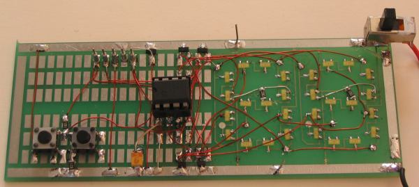
PARTS LIST
PIC12F629 version
with SM LEDs |
|
RESISTORS
(All surface mount 1/10th watt)
5 - 47R marked as 470
1 - 1k "
" 102
1 - 22k " " 223
CAPACITORS
1 - 100n surface mount
1 - 10u tantalum surface mount (106)
SEMICONDUCTORS
1 - surface mount diode
1N4148
(a6p)
2 - BC847 - surface mount (1F)
2 - BC856
- surface mount (3B)
1 - PIC12F629 Micro (00-99 Counter)
1 - on/off slide switch
2 - tactile switches
1 - 8 pin IC socket
5 - machine pins
28 - yellow surface mount LEDs (30)
Orange screen 4.5cm x 3cm
30cm - fine solder
20cm - fine tinned copper wire
50cm - 0.025mm enamelled wire
1 -
2 Digit Counter
PC Board
(Experimenter Board) |
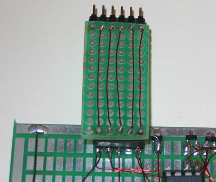
You will also need the 6 pin to 5 pin
adapter for "In Circuit Programming" to connect between
the PICkit-2 programmer and the Project ($1.50): A PC
board is being produced for the adapter.
GOING FURTHER
Now that you know how to access
each of the segments i the left and right displays, you can
produce all sots of programs.
Some of the ideas we have in the pipeline include a timer.
How many times have you burnt something or forgotten to ring
someone back after an hour?
This handy timer has a few buttons and by simply pressing a
button it will count down and sound a piezo when the time
has expired.
This will be one of the next projects but you can get in
first and try your hand at programming.
All you need do is add a buffer to drive a piezo and since
all the lines are fully occupied, this will require a clever
bit of interfacing.
I will give you a clue how to do it.
The output of one of the lines will contain a delay circuit
(say 0.2 second) and when this is kept low, the other line
can be used to drive the buffer transistor, as shown in the following
diagram:
To order the kit,
send
an email
to us and we will reply with the details of how to order
etc.
If you have any questions on how the circuit works or how to
add different features,
email
the author and your answer will
be posted here:
P1 P2
P3 P4(RF
Link)
P5
20/6/09
|