|
37 SENSOR
TESTING MODULE
P2 |
This section of the discussion describes
the circuits and components in the 37 SENSOR MODULES.
The worst component in the modules is the LM393 IC. It is a dual
comparator and the output has a single transistor that will pull the
output LOW. It has absolutely no capability of taking the output HIGH
and this creates considerable problems with interfacing the module to an
output stage.
SOUND DETECTION
Both these modules are the same. They are quite
useless. The audio output (AO) is directly from the electret
microphone and it will be about 200mV when the pot is turned to a
fairly low resistance and the electret mic will be driven very hard.
The digital output (DO) only produces an output at a very critical
setting of the pot and this will never be reliable.
There is no practical, reliable use for this module. The chip is not used
for the Analogue output and the digital output is very very critical
with the adjustment of the pot. |
LINE FOLLOWER - DISTANCE SENSOR - OBJECT DETECTION
DISTANCE SENSOR
LINE FOLLOWER
Both these modules detect the presence of an
object by detecting Infra red light from the transmitting LED to the
receiving LED/Receiving Module.
You will need to experiment with them to see which one is more
suitable for your application.
KY-032 is more sophisticated.
The 555 chip produces a frequency of exactly 38kHz and sends this
frequency in the form of pulses to the transmitting IR LED. The
strength of these pulses is determined by the current-limiting 10k
pot.
The
receiving module has circuitry within the module consisting of a
filter that only detects 38kHz.
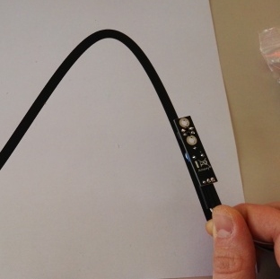
HOW TO SET UP KY-032 MODULE
Turn the 10k behind the IR LED (the left-hand pot in the image below) fully clockwise and the red LED will
illuminate. Now turn it slightly anticlockwise until the LED goes
out.
Now put your hand 5cm from the front of the module and turn the pot on the
right until the LED comes on again. If you turn it too far, the LED
will go off again. This pot adjusts the frequency of the 555 and the
IR receiver only detects 38kHz pulses.
Move your hand away slightly and adjust the left pot until the LED
comes ON. .
If you turn the left pot fully clockwise, you will be able to pick up your
hand at a greater distance.
The 38kHz signal is called the CODING FREQUENCY and allows the module to detect your hand when the
level of illumination in the room changes. You will be able to turn
on your desk lamp and the module will work perfectly.
KY-032 MODULE
INTERFACING THE
KY-032 MODULE
Connecting the KY-033 module to a device such as
a relay, buzzer or powerful LED is not easy.
The Signal Out line is pulled LOW by a transistor in the Receive
Module and there are no components that pull the line High.
The transistor in the module is only capable of handling 50mA to
100mA.
The simplest solution is to add a BUFFER transistor.
This transistor is called AN EMITTER-FOLLOWER PNP DRIVER and will
pull the LOAD low when the Receiver Module detects an object.
This arrangement will only work on 5v supply as the signal out
line only rises to a maximum of about 5v, (to turn OFF the load) so
that if the load is connected to 12v, the emitter-to-base voltage
will be (may be) 7v, and the load may not turn OFF. It all depends
on "if and how" the signal out line is prevented from rising
above 5v.
KY-033 MODULE
- LINE FOLLOWER
Module KY-033 has a much shorter range of 1cm to 2 cm and when you
turn on your desk lamp, the module does not work. .
This is because the receiving LED picks up infra-red illumination
from every source.
The photo on the left shows one of the applications for KY-033 module,
commonly called a "Line-Follower."
The black line absorbs the infra-red and the white paper reflects
it.
Turn the pot until the module picks up the condition when the module
is detecting the white paper.
The output of the LM 393 only pulls LOW and there are not components
taking the output high.
This means the only simple way to add an output device is via a PNP
transistor as an
EMITTER-FOLLOWER DRIVER as shown in the circuit above: "ADDING A
BUFFER TRANSISTOR."
The IR LED and IR receiving transistor in the TCRT5000 module are
designed for a range from 0.2mm to 15mm.
When the received Infra red is very bright, the receiving transistor
turns on more and the voltage on the output pin reduces. This makes
it lower than the voltage selected by the pot and thus the output of
the comparator goes LOW and turns on the output LED.
This module is very effective for what it is designed for and you
cannot get any more than 1.5cm range.
|
KY-023 JOY STICK
The Joy Stick can be connected to a servo,
using a 555 IC as the PWM generator:
The supply for the servo must be separate from the 555 section because
the 555 picks up noise from the servo and makes the motor vibrate all
the time.
This circuit works in the "Y-direction." Build another circuit for the
"X-direction."
Adjust the 10k pot for the centre of travel and use the Joy Stick to
produce left and right action. |
LEVEL CONVERTER - LEVEL SHIFTER
Although this circuit is very clever, it takes a lot of
understanding to see how it works, and because there are a number of
modules on the web, you have to know how to connect them.
Here is the basic circuit for the LEVEL SHIFTER:
 |
This
is the same circuit as shown on the web and in all discussions.
I don't understand it AT ALL and I don't expect you to understand it
either.
It has to be described in very fine detail and each of the 4 operations
of the circuit has be described clearly, so you are not befuddled by its
operation.
LV means 3.3v and HV means 5v.
Input A can be 0v or 3.3v This is two of the operations of the
circuit.
1. When input A is 0v, the output is 0v.
2. When input A is 3v3, the
output is 5v.
|
The circuit also works the other way.
When B is an input, A is an output.
3.When B is 0v, A is 0v.
4. When B is 5v, A is 3.3v.
This is called a bi-directional circuit.
When you understand how the circuit works, you will be able to work out
the meaning of the numbers and letters on the module. Some modules have two of the above circuits
and some have four.
 To
make the circuit easy to understand, we have redrawn it with the 5v and
3v3 power rails at different heights. To
make the circuit easy to understand, we have redrawn it with the 5v and
3v3 power rails at different heights.
For our first explanation:
Input A is HIGH.
 The
voltage between S and G is zero because the G pin is at 3v3 and the input
line is at 3v3. The
voltage between S and G is zero because the G pin is at 3v3 and the input
line is at 3v3.
This means the MOSFET is not turned ON and it is just like it being
removed from the circuit.
This means the input line is not connected to the output.
The only component in the circuit that is connected to the output is the
10k.
This resistor will pull the output HIGH - (providing there is NO LOAD on
the output).
 Input A is
LOW. Input A is
LOW.
When
the input is LOW, the BSS 138 MOSFET sees a voltage of 3.3v between the
Gate and Source leads and it turns ON. It effectively joins the Source
and Drain leads and since the source lead is at 0v, the D lead will
be at 0v and thus the output of the circuit will be 0v.
NOW REVERSE THE CIRCUIT:
 The
input is now on the 5v part of the circuit. The
input is now on the 5v part of the circuit.
When the input is 0v, the D lead of the MOSFET is at 0v and the
Schottky diode inside the MOSFET sees this zero voltage and it produces
a characteristic voltage across its terminals of about 0.3v and it drags
the output down to about 0.3v, which we have called 0v.
 When
the 5v input is HIGH, the MOSFET disappears from the circuit and the 10k
on the output pulls the output HIGH. When
the 5v input is HIGH, the MOSFET disappears from the circuit and the 10k
on the output pulls the output HIGH. (We have only described the
operation of the circuit for the 4 DIGITAL STATES. As the input voltage
rises and falls, the MOSFET and Schottky diode have a varying effect
during the transition.) 4 CHANNEL MODULE
 This
is called a 4 CHANNEL LEVEL SHIFTER MODULE. This
is called a 4 CHANNEL LEVEL SHIFTER MODULE.
There are 4 MOSFETS - one for each channel and you need to connect
the module to 3.3v, 5v and 0v. Connect to both GND on the board as some
modules do not have these connected together.
Take any of the 5v lines to your 5v project and the corresponding 3v3
lines to your 3v3 project.
You can send a signal from any or all the 5v lines to the 3v3 project or
any of the 3v3 lines to the 5v project at any time and change the
direction at any time.
There are also 8-Channel versions of this module.
Note: All channels use the MOSFET arrangement - some module don't !!!
HERE'S A TRAP:
Some of the modules do not emphasize the fact that some of the channels
only work ONE WAY. They are voltage dividers and have two 10k resistors.
This means the maximum output voltage will be slightly less than 2.5v
and this is sufficient to produce a high for the 3v3 module.
These channels will only produce 1.65v in the reverse direction.
 This
is a very handy module because it provides bi-directional LEVEL
SHIFT for 2 lines and a 3v3 regulator. This
is a very handy module because it provides bi-directional LEVEL
SHIFT for 2 lines and a 3v3 regulator.
You can buy the module for less than $1.00 and it is a very cheap way to
get a 3v3 regulator.
The on-board 3v3 regulator means you do not have to provide 3v3 for the
low-voltage projects you are interfacing to and the regulator will
deliver about 120mA.
Only the red module is available on the web.
It was obviously copied from the blue module and released very cheaply.
Some of these modules were originally $4.00 or more, but the Chinese
have competed with each other to bring the price down to less than 40
cents when ordering 10 units.
The easiest way to differentiate the various models is to count the
number of transistors (MOSFETS).
 The
2 data lines are bi-directional and you can substitute the 4-channel
module and provide the 3v3 for the project as a separate power supply. The
2 data lines are bi-directional and you can substitute the 4-channel
module and provide the 3v3 for the project as a separate power supply.
Connecting the 2-Channel module and using the
3v3 regulator
to power a 3v3 project
You can make a LEVEL SHIFTER with transistors:
It
is hardly worth constructing a transistor circuit when a Level Shifter
module costs as little as 50 cents when you buy more than one and you
get a neat PC board and connecting pins.
You can combine a 2-Channel with 4-Chanel Module to get 6 channels or two
4-Channel to get 8-Channels.
 |
| |
| |
13-8-2018
|