|
|
|
|

This 4 Digit Up/Down
Counter has all the features you need. And they are all ON THE PC BOARD.
4
Digit Counter
29/11/2014
This project is as old as Methuselah but it's very handy for anyone
producing or packaging a product or "counting their chickens."
You don't need
any extra relay or buzzer and the up/down switches have inputs for
remote switching as well as a 10-pin connector so the project can be
mounted on a cabinet.
It also has a very easy to use PRE-SET using 2 buttons, to quickly load
any value.
Simply press SET and the display will show - - -
-
Use the INC button to increment the units display and press
SET. The
tens display can now be incremented, then the hundreds and thousands.
Press SET and the display will show 0000 and the buzzer will screech.
Press DOWN and the preset value will appear. When the count reaches 0000
the buzzer will sound and the relay will activate during the time when
0000 in on the display.
The counter will then show the preset value when the DOWN button is
pressed and counting can continue until the display is zero.
There is almost nothing else to know as all the "workings" are contained
in a micro and if you want to learn about programming this
microcontroller, we have separate projects to get to started.
In addition, we show how to create your own PC boards using the simplest
software package that "doesn't fall over" and doesn't frustrate.
Don't even attempt to put this project together unless you have a fine
tipped, temperature controlled soldering iron, tweezers, fine solder and
a steady hand.
Everyone I have given prototypes to have enjoyed the surface-mount
components and I have to admit it is the most rewarding part of
construction.
Once you go to surface-mount - you never go back.
Logic Probe Test Points have been added to the latest batch of
boards as these should be included so you can check the
running of the program and for test purposes.
All the testing of the project will be covered in future articles after
we present two pieces of TEST GEAR - a LED tester and LOGIC PROBE. 
The 4-Digit Up/Down Counter Circuit with Pre-set
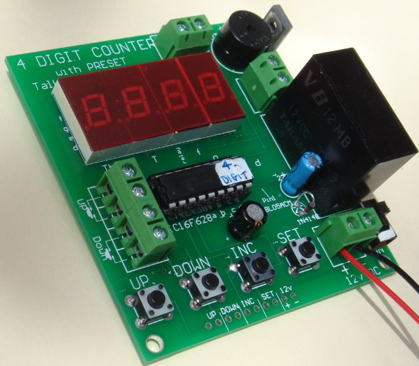
Up/Down can be controlled remotely
and the buzzer sounds
when the
display is 0000.
All the switches and power can be taken to a control panel via
the
pins on the bottom of the board.

The project uses a
PIC16F628 chip and the drive-lines are
connected to transistors to produce a bright display.
All the components are on the underside of the board.

The top output has 12v on
the left output and the right
output is connected to the BD679 transistor.
You can place a load on these connections
up to 2 amp - the BD679 will carry up to 8 amp if it
has a large heatsink.
The letters on the board refer to
the display segments and the
surface-mount transistors driving each segment.
These have been added to assist with servicing.

The underside of the board has all
the surface-mount
components for driving the display at high brightness.
We have not relied on the 20mA output of the chip to drive the segments.
The 78L05ACM is a surface-mount regulator: 5v, 100mA
Construction
Start by fitting the
surface-mount transistors, resistors and capacitors, as well as the
5v regulator and 10u tantalum capacitor, to the
underside of the board. Then fit the 4 displays, terminal bocks,
tactile switches, 18 pin IC socket, 2 electrolytics, BD679 transistor,
1N4148 diode, on/off switch and finally the relay. The 10-pin connector can be
fitted if you are mounting the board and using remote switches.
Fit the PIC microcontroller chip containing 4-Digit routine, connect 12v to the input
terminals and switch the project ON.
The display will show 0000 and the buzzer will sound.
Use the SET button to create a pre-set value and press the
DOWN
button to start the count.
The buzzer will sound when the display reaches 0000.
The buzzer is
classified as an active device as it has its own internal
oscillator, coil and metal diaphragm to produce an output when
DC is applied.
It is called an electromechanical buzzer.
PARTS LIST
$25.00
plus $6.50
post
Order a kit
7 - 47R resistors (470)
1 - 150R SM resistor (151)
2 - 220R SM resistors (221)
6 - 2k2 SM resistors (222)
4 - 4k7 SM resistors
3 - 100n SM capacitors
1 - 10u SM electrolytic
1 - 22u electrolytic 16v
1 - 100u SM electrolytic 16v
1 - 1N4148 diode
12 - BC848 SM transistors
1 - BD679 Darlington transistor
4 - TIL 313 displays or equiv
1 - TV-3 12v DPST relay
1 - 78L05ACM 5v regulator IC
1 - PIC16F628 microcontroller (4 Digit program)
1 - 5v buzzer
1 - 18 pin IC socket
5 - 2-pin terminal blocks
1 - 10 pin 90° double-ended connector strip
4 - tactile buttons
1 - mini slide switch
30cm very fine solder
1 - 4 Digit Counter PCB