|
Page
9:

THE
LIGHT EMITTING
DIODE
In
this set of projects, a small light emitting device is used in
projects 1, 2, 3 and 4 to show that a circuit is working. It looks
like a very tiny red or green globe but in fact it does not have a
filament and does not get hot - so it's not a globe. It's a
solid-state device that never burns out and consumes very little
current. It is called a Light Emitting Diode or LED for short.


5mm Red LED 3mm
Red LED
It
is one of the most amazing electronic devices to be invented and you
will have seen it used in flashing tail lights for bicycles and as "ON" indicators for electronic appliances and in many types
of 7-segment number displays.
Even though this component looks very simple it has a number of
requirements that have to be met to make it work properly and that's
the purpose of these experiments.
Here are some of the characteristics and requirements of a LED:
A LED must have a resistor in series with one lead to prevent it
burning out.
A LED will only work when connected around the correct way.
A LED produces a characteristic voltage across its terminals and this
voltage is constant, no matter how bright the LED. The voltage is
1.7v for red LEDs, 2.1v for green and 2.3v for orange LEDs. This voltage
is slightly higher for some LEDs, depending on the manufacturer and High Bright
devices have slightly different characteristic voltages.
But for our particular devices, it remains constant.
A LED can be turned on for a very short period of time and your eye
will extend the time (due to a phenomenon called Persistence Of
Vision). That's why we can pulse a LED very briefly and repeat the
process at a high frequency and the LED will appear to be ON all the
time.
The only thing you cannot get from a LED is white light. You can get
red, green, yellow, orange or blue, but not white. The colour is
determined by the crystalline material used in the centre of the LED.
The casing or body is sometimes red, green or orange etc to help
enhance the colour of the emission from the crystal and this is called
a diffused
LED. If the body is clear, the colour produced by the crystal will
depend on the type of crystal giving off the illumination. White light
cannot be produced by a single emission - the only way to get nearly white
light is to
combine red, blue and green LEDs together and the eye will merge the
colours to get white.
The symbol for a LED is shown below:
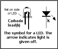
The line on the diagram corresponds to the cathode lead and this is
generally the shorter lead.
You cannot always be certain of this as we have found some LEDs are
made in reverse or sometimes the two leads are the same length.
When we are talking about the leads, we do not describe them as
"positive" and "negative" we only say anode and
cathode. Most of the time we only refer to the CATHODE lead.
A small flat on the side of the body of a LED indicates the cathode
lead - this is very helpful to remember as it identifies the correct
placement of the LED when fitting it to a project.
If you do not know which lead is the cathode, connect it to a 9v
battery with a 220R or 470 ohm resistor in series with one lead. The
LED will illuminate when the cathode lead is connected to the negative
terminal of the battery.
The normal current required by a LED is 10mA (milliamp). The LED will
still operate on currents as low as 1mA and the maximum continuous
current is 25mA.
For a particular current flow, some LEDs are brighter than others.
This is due to their efficiency. Light output is measured in
milli-candella. Most LEDs have an output of about 20mcd and these are
used as "ON" indicators. Better quality LEDs are 100, 200
and 500mcd and these are called High Bright. Super High Bright LEDs
have an output of 500mcd, 1,000mcd, 2,000mcd and 5,000mcd.
5,000mcd = 5 candella and these LEDs produce a
light beam suitable for a key-light torch.
TESTING A
LED
Before fitting the LEDs to the projects in this e-book, they can be
tested to find the cathode lead. Simply connect one of the 220R or
470R resistors to one of the leads and connect to a 9v battery as
shown in the diagram.
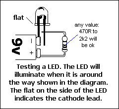
If
the LED does not illuminate, turn the LED around. This testing will
not damage the LED. (Do not connect the LED directly across the 9v
battery as this will damage the crystal inside the LED.) When the LED
illuminates, the cathode (k) lead of the LED will be connected to the negative terminal of the battery.
FITTING A
LED
The LED is fitted to the PC board so that the cathode lead (the shorter
lead) goes down the hole marked with the line on the overlay. Refer to
the diagram
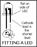
Sometimes
a small flat can be seen on the side of the LED but this is very hard
to find on 3mm LEDs. The best is to reference from the shorter lead
but if you have cut the leads, you will have to test the LED as shown
above before fitting it.
Don't forget to solder LEDs very quickly as they can be easily
damaged when soldering and their light output will be reduced.
|