5x7 Display Experiments Page10
![]()
EXPERIMENT-26 LED
Dice The instruction for Button A was then added to Main6 and a sub-routine (called XX)
was added that CALLed table1. The result from the table is a number from
1 to 7. This is where a clever feature comes in. If the table value is
"1", the result after decrementing is zero and this indicates
the end of table. The "table pointer" (also called a Jump Value)
is zeroed (file 1C) so that the program starts at the top of the table
again. This gives us 6 remaining values and by decrementing the result
from the table the program can be sent to Face 1, 2, 3,4 5, or 6.
This experiment is very similar to
some of the LED Dice programs you have seen in other magazines - only it's BETTER!
Instead of using a single LED to indicate the numbers on the face of a dice
(actually a single Dice is called a Die!),
we have used a group of LEDs. It's difficult to get a good pattern for the
spots on a 5x7 matrix but we have done a reasonable job. Your challenge is to
improve the layout or produce a special display.
Once the pattern for the numbers has been worked out on paper (as
shown in the diagram below), the
values can be put into a table or set of sub-routines. Five values are
needed for each of the six numbers as the display shows the complete face of
the dice.
The next thing is to decide on the random number generator. We have already
explained the two ways of generating random numbers; via a computer program
or via a table. On a previous page we generated random
numbers via a computer program for a tumbling
dice and found the program was heavily biased towards two of the
numbers. We then had to "weight" or modify the program to create
an even distribution.
By producing a table, you can adjust any value to suit a particular outcome
and not have to worry about the "accuracy of statistics" to come to your
rescue thousands of tosses down the track!
So, where do you start? I simply looked at the previous experiments and in
Expt 18, found exactly what I needed. It shows how to scan 5 cells of an
animation. So, I copied the 100 lines of code and got a very good start. From
the diagram below, the value for each file was placed in each sub-routine
and a sixth sub-routine included in the program. The Main program was changed
to allow the six Face sub-routines to be called and the project
was run and tested to see the result on the display.
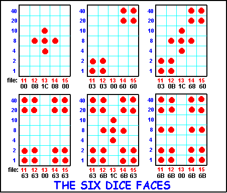
Each of the Face sub-routines loads 5 files with values that will illuminate
the required LEDs on the display and the micro is sent to the Scan routine
to provide one pass of the display. To scan the display for 1/10th of a
second, for example, requires a number of loops of the Scan routine and this
is achieved in the Main routine. The "on time" for each
number can be adjusted
by the value loaded into file 0C. We have progressively increased this time
to give the effect of the dice slowing down.
The main routine displays 5 brief numbers on the display then settles in a
loop with the sixth value. Pressing button A will take the micro out of the
loop.
The Jump Value for the table is incremented in the Main routine.
The number of values in the table is not divisible by 6 so that the program will
go through the table a number of times before the same sequence is
repeated.
|
Experiment-26
for "5x7 Display" Project
;PIC16F84 and only F84 chip �;LED Dice Start ORG 0x00 BSF 03,5 ;Go to page1 for setting-up the ports MOVLW 04h ;Put 04 into W MOVWF 05h ; to make RA2 input for button A MOVLW 00h ;Put 00 into W MOVWF 06h ;and make port 6 (port B) all output BCF 03,5 ;Go to page0 for programming MOVWF 1Ch GOTO Main Table1 ADDWF 02h,1 ;Add W to Program Counter����� RETLW 03h RETLW 07h RETLW 06h RETLW 04h RETLW 02h RETLW 06h RETLW 07h RETLW 03h RETLW 05h RETLW 02h RETLW 02h RETLW 03h RETLW 05h RETLW 04h RETLW 02h RETLW 07h RETLW 06h RETLW 07h RETLW 04h RETLW 03h RETLW 02h RETLW 05h RETLW 07h RETLW 06h RETLW 03h RETLW 02h RETLW 02h RETLW 03h RETLW 04h RETLW 05h RETLW 04h RETLW 03h RETLW 07h RETLW 04h RETLW 06h RETLW 07h RETLW 02h RETLW 03h RETLW 04h RETLW 05h RETLW 01h Face1 MOVLW 00h ;place the 5 values into the 5 MOVWF 11h ; files to produce the first face MOVLW 08h MOVWF 12h MOVLW 1Ch MOVWF 13h MOVLW 08h MOVWF 14h MOVLW 00h MOVWF 15h GOTO Scan Face2 MOVLW 03h ;place the 5 values into the 5 MOVWF 11h ; files to produce the second face MOVLW 03h MOVWF 12h MOVLW 00h MOVWF 13h MOVLW 60h MOVWF 14h MOVLW 60h MOVWF 15h GOTO Scan Face3 MOVLW 03h ;place the 5 values into the 5 MOVWF 11h ; files to produce the third face MOVLW 0Bh MOVWF 12h MOVLW 1Ch MOVWF 13h MOVLW 68h MOVWF 14h MOVLW 60h MOVWF 15h GOTO Scan Face4 MOVLW 63h ;place the 5 values into the 5 MOVWF 11h ; files to produce the fourth face MOVLW 63h MOVWF 12h MOVLW 00h MOVWF 13h MOVLW 63h MOVWF 14h MOVLW 63h MOVWF 15h GOTO Scan Face5 MOVLW 63h ;place the 5 values into the 5 MOVWF 11h ; files to produce the fifth face MOVLW 6Bh MOVWF 12h MOVLW 1Ch MOVWF 13h MOVLW 6Bh MOVWF 14h MOVLW 63h MOVWF 15h GOTO Scan Face6 MOVLW 6Bh ;place the 5 values into the 5 MOVWF 11h ; files to produce the sixth face MOVLW 6Bh MOVWF 12h MOVLW 00h MOVWF 13h MOVLW 6Bh MOVWF 14h MOVLW 6Bh MOVWF 15h GOTO Scan Scan BSF 05,1 ;Reset 4017 NOP BCF 05,1 MOVF 11h,0 ;Move file 11 into W MOVWF 06h CALL DelD MOVF 12h,0 ;Move file 12 into W MOVWF 06h CALL DelD MOVF 13h,0 ;Move file 13 into W MOVWF 06h CALL DelD MOVF 14h,0 ;Move file 14 into W MOVWF 06h CALL DelD MOVF 15h,0 ;Move file 15 into W MOVWF 06h CALL DelD RETURN DelD DECFSZ 1Bh,1 GOTO DelD MOVLW 00h ;Zero port B to prevent mirroring MOVWF 06 Clk BSF 05,0 ;Clock the 4017 NOP BCF 05,0 RETURN XX MOVF 1Ch,0 ;Move 1C to W CALL Table1 MOVWF 1Dh ;Move W to 1D for decrementing DECFSZ 1Dh,1 GOTO XX1 MOVLW 00 ;Detects end of table MOVWF 1Ch ;Zero 1C to start at top of table GOTO XX XX1 DECFSZ 1Dh,1 GOTO XX2 GOTO Face1 XX2 DECFSZ 1Dh,1 GOTO XX3 GOTO Face2 XX3 DECFSZ 1Dh,1 GOTO XX4 GOTO Face3 XX4 DECFSZ 1Dh,1 GOTO XX5 GOTO Face4 XX5 DECFSZ 1Dh,1 GOTO Face6 GOTO Face5 Main MOVLW 30h ;Each 10h represents 100mS MOVWF 0Ch Main1 CALL XX DECFSZ 0Ch GOTO Main1 INCF 1C MOVLW 40h ;Each 10h represents 100mS MOVWF 0Ch Main2 CALL XX ;Display Face for 400mS DECFSZ 0Ch GOTO Main2 INCF 1C MOVLW 50h ;Each 10h represents 100mS MOVWF 0Ch Main3 CALL XX ;Display Face for 500mS DECFSZ 0Ch GOTO Main3 INCF 1C MOVLW 60h ;Each 10h represents 100mS MOVWF 0Ch Main4 CALL XX ;Display Face for 600mS DECFSZ 0Ch GOTO Main4 INCF 1C MOVLW 70h ;Each 10h represents 100mS MOVWF 0Ch Main5 CALL XX ;Display Face for 700mS DECFSZ 0Ch GOTO Main5 INCF 1C Main6 CALL XX ;Display until button A pressed BTFSS 05,2 ;Test for button A GOTO Main6 GOTO Main END |
|
|
||
|
:100000008316043085000030860083129C00A628E9 :1000100082070334073406340434023406340734C8 :100020000334053402340234033405340434023416 :1000300007340634073404340334023405340734F7 :1000400006340334023402340334043405340434F3 :1000500003340734043406340734023403340434DC :100060000534013400309100083092001C309300B8 :10007000083094000030950074280330910003305C :100080009200003093006030940060309500742836 :10009000033091000B3092001C30930068309400C4 :1000A0006030950074286330910063309200003016 :1000B000930063309400633095007428633091009E :1000C0006B3092001C3093006B30940063309500CD :1000D00074286B3091006B309200003093006B30CD :1000E00094006B3095007428851400008510110869 :1000F0008600872012088600872013088600872044 :1001000014088600872015088600872008009B0BAE :1001100087280030860005140000051008001C0820 :1001200008209D009D0B972800309C008F289D0B78 :100130009A2832289D0B9D283D289D0BA0284828F1 :100140009D0BA32853289D0B69285E2830308C0016 :100150008F208C0BA8289C0A40308C008F208C0BA1 :10016000AE289C0A50308C008F208C0BB4289C0A3F :1001700060308C008F208C0BBA289C0A70308C0069 :100180008F208C0BC0289C0A8F20051DC428A62810 :00000001FF |
Go to the next page of experiments: 5x7 EXPERIMENTS: Page-11
![]()