AUTOMATIC AA
NICAD CHARGER
Charges AA
cells on a 5-hour or 14-hour rate
with automatic turn off
![]()
Rechargeable batteries are very popular for use in all
sorts of devices, especially those requiring a high current.
The most common type of cell is the AA or penlight and although thousands have
been sold, there are very few low-cost chargers to keep them in tip-top
condition.
Most of them simply charge them at the slow rate and never turn off - you have
to remember. Charging a cell for longer than necessary reduces its life so it’s
important to cease the charging operation when the time is up.
To solve this problem we have designed an automatic charger to charge any
number of AA cells, from 1 to 8 and turn off when the cells are
charged.
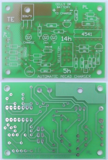
|
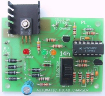
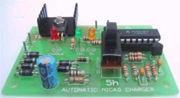
Two photos of the Automatic AA Nicad Charger |
| Automatic AA Nicad Battery Charger Circuit |
Rechargeable batteries are very popular for use in all sorts of devices, especially those requiring a high current.
The most common type of cell is the AA or penlight and although thousands have been sold, there are very few low-cost chargers to keep them in tip-top condition.
Most of them simply charge them at the slow rate and never turn off - you have to remember. Charging a cell for longer than necessary reduces its life so it’s important to cease the charging operation when the time is up.
To solve this problem we have designed an automatic charger to charge any number of AA cells, from 1 to 8 and turn off the power when the cells are charged.
When designing this project we assumed two things:
1. The user will only be charging AA cells, and
2. The cells will be almost totally discharged.
This will normally be the case as most nicads are used until the equipment starts to falter, such as a toy car going slow or a radio starting to distort. This is when the cells must be removed and recharged as it is an indication that one of the cells has reached its point of complete discharge and any further use will allow current to flow through the cell in the reverse direction and damage it.
All our discussion in this article will concentrate on the AA cell as the charger is specifically designed for this type of cell.
However C cells can be charged, simply by charging them at the 5 hour rate for two complete cycles. Just disconnect and re-connect when the first 5-hour timing is up.
|
Automatically charges AA cells at 5Hr rate or
14Hr rate. Charges 600mAHr AA cells and 1.2AHr AA cells. |
This keeps the circuit simple and prevents possible
overcharging of any of the cells, if you are alternately charging AA and C
cells.
There are currently two types of AA nicad cells on the market.
| Also Required: 8.5v AC 400mA plug pack or 15v AC 1amp transformer Use 9v5 tap for up to 8 x AA cells or 15v tap for 12v Gel cell battery. |
The ampere-hour capacity of the old-style cell is
450mAHr. Some of them are 500mAHr, 550mAHr or 600mAHr.
Newer AA cells are 1.1AHr or 1.2AHr. Fortunately, most cells have the amp hour
rating on them and this will help you set the charge-rate and/or time.
The first thing you cannot do is combine old-style cells with the new style. If
you do, you will either over-charge the old-style ones or only partially charge
the new ones. Stick to one type of cell at a time and select the time and
charge-rate you require.
If you intend to charge the 1.2Ahr cells, we have added two components on the
circuit diagram to change the charging current to 90mA for 14 hours to cater
for this type of cell. This consists of a 12R resistor and slide switch that
can be mounted on the top of the box and labelled 600mAHr when in one position and 1.2AHr in the
other position. We have not provided a quick charge
facility for the 1.2AHr cells.
Instead of adding this switch, you can simply give them three cycles at the 5
hour-rate or two cycles at the 14 hour rate.
We have lumped all the old-style cells in to one category as the difference
between a 450mAHr cell and 600mAHr will be very small as far as the charging
is concerned and in use you will hardly detect the difference as you will
rarely be able to use all the energy in a cell.
The full capacity of a 450mAHr or 600mAHr cell is only obtained when the cell
is discharged under fairly low laboratory conditions such as 10 - 15mA. Most
toys and radios take 2 - 30 times more than this and the amp-hour capacity you
get from the cell falls considerably as the current-demand increases.
Every cell and every condition is different but you can easily reduce the
Amp-hour capacity to 200 - 300mAHr if you use it in something that takes 200 -
300mA.
That's why you only get one or two hour's life (or even less) out of a set of
cells when you are using them in a toy such as a remote control car.
However the 1.1 and 1.2AHr cells will provide twice the energy of the old-style
cells, under the same conditions.
No matter which type of cell you choose, the cost of powering high-performance
toys will drop considerably by using rechargeable types.
And with this charger you can keep them fully charged without over or under
charging.
To get the best performance out of rechargeable cells you must remember four
things:
1. Cells must not be left in an uncharged state,
2. They must not be overcharged,
3. They must not be totally discharged (cell voltage must remain above 1v) and
4. They must not be discharged at more than 500mA (for more than a few
seconds).
Any abuse of these rules will reduce the capacity of the
cell. Nicads (and all their closely allied variations) also have another
unusual characteristic that reduces the capacity. It's called "memory."
If you
recharge a cell that is only say 25% discharged, the cell will think its new
capacity is only 25% of the true value. Thus you will only be able to get 25%
of its energy before the cell starts to falter.
This means it is very important to almost fully discharge a cell before
starting the charging process.
Some of the new cells do not have this "memory" problem but their cost at the
moment is more than twice the older style cells - so, it's the old saying: you
get what you pay for. This project will enable you to care for AA cells and
even rejuvenate some of them that have generated a memory. If a cell with a
memory is discharged fully and charged completely, over a number of cycles, its
poor performance can be improved and some can be restored to near full
capacity. There is another device, called a nicad Zapper, that will rejuvenate
some of the cells that have developed an internal fault, such as a short, that
prevents it from receiving a charge. Now back to our circuit.
HOW THE CIRCUIT WORKS
The heart of the circuit is a 4541 timing chip. It has a built-in oscillator
that requires only two external components for timing. A chain of sixteen
binary dividers inside the chip is capable of producing a division of 65,536.
With this we can produce very long time delays by making the internal clock of
the chip a low-frequency oscillator and using it to clock the divider chain.
The other feature of this project is the constant-current charging circuit that
allows you to fit any number of cells, up to 8, in the charging holder. Some
chargers only accept 1,2 or 4 cells at a time while ours will accept any number
providing the unused parts of the holder are connected with a jumper lead to
make a complete charging path.
The BC 547 and BC 557 in the Automatic charger detect when a battery has been
fitted to the circuit and turn on the 4541 timing chip. The green "Charge" LED
comes on to show the battery is charging.
The orange LED shows you have selected the 14 hour rate and the red LED
indicates you have selected the 5 hour rate.
CHARGING
During charging, no gases are generated. However during the latter part of the
charge-cycle, during overcharge and during heavy discharge, hydrogen and
oxygen gases are generated as well as electrolyte fumes. These gases can
normally react with each other and not increase the pressure inside the cell
however if they are produced at a fast rate, this equilibrium condition cannot
be maintained and the pressure inside the cell builds up.
A pressure release valve is built into the cell but any gases that escape will
include some of the electrolyte in the fumes and the cell will eventually dry
out. For this reason it is important to limit the charging cycle.
ADAPTING THE CHARGER
The charger can be adapted to charge AA, C, or D cells or any combination of
these by modifying the circuit slightly or by adding extra constant-current
sections as shown in the circuit diagram below.
It will even charge 1.2AHr or 1.9AHr Gel cells of the 12v
type as used in alarm systems, simply by making sure the rail voltage is above
18v, (but not more than 22v) to take into account the 3v minimum voltage drop
across the BD 679 transistor.
If you want to charge only C or D cells, the circuit can be modified by
changing the current-determining resistors R1 and R2 as follows:
|
C cell |
D cell |
|
|
14Hr rate |
4R7 |
2R2 |
|
5Hr rate |
2R7 |
1R0 |
|
The current-determining resistors for “C” and "D" cells |
The wattage of the resistors in the above table will have to be taken into account due to the high current that will be flowing through them The following table shows you how to "make-up" the resistors:
|
4R7 = two 10R resistors in parallel |
2R2 = 4 x 10R |
|
2R7 = Four 10R resistors in parallel |
1R = two 2R2 10R resistors in parallel |
If you want to charge AA, C and D cells, you can add
extra circuitry consisting of the constant-current section shown above to cater
for the C and D cells.
To charge these cells, the BD 679 transistor will have to be heat-sinked with
a larger heat-sink than is provided in the kit and the plug pack will have to
be upgraded.
For a C cell, the 14 hour rate is 150mA and the 5 hour rate is 300mA. For a D
cell, the 14 hour rate is 350mA and 700mA for the 5 hour rate.
Most plug packs have very poor regulation and the output voltage will drop
considerably when full current is delivered. You will need a 500mA plug pack
to deliver 350mA and a 1amp plug pack to deliver 700mA. Otherwise a 300mA or
400mA plug pack will be sufficient for the AA version.
Alternatively you can charge C and D cells with the original circuit by giving
these cells two or three charge-cycles as show in the following table:
|
CHARGING: |
5 Hour rate: |
| C cells |
2 time-cycles |
| D cells |
5 time-cycles |
When choosing a plug pack, you must be careful not to supply the circuit with more than 15v AC as this becomes 22v DC when rectified and will create extra heat loss in the transistor.
|
The PCB, showing the overlay and the track work |
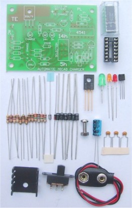
|
Automatic AA Nicad Charger kit, showing all the components |
|
PARTS LIST |
|
1 - 8R2 1 - 18R 1 - 470R 1 - 1k 1 - 4k7 5 - 10k 1 - 1M2 2 - 3M3 3 - 100n monoblock capacitors 1 - 100u 25v PC mount electrolytic 1 - 1N 4148 diode 6 - 1N 4004 power diodes 1 - 12v Zener diode 400mW 1 - BC 547 transistor 1 - BC 557 transistor 1 - BD 679 transistor 1 - 4541 IC 1 - 14 pin IC socket 1 - 3mm orange LED 1 - 3mm red LED 1 - 5mm green LED 1 - battery snap 1 - DPDT slide-switch 1 - 10cm tinned copper wire 1 - Auto Nicad Charger PC board |
|
Extras: |
|
1 - plug pack 1 - 2 cell or 4 cell AA battery holder 1 - 12R (for charging 1.2AHr cells) 1 - slide switch 1 - 3cm x 5cm heat-sink 1 - 12mm bolt with nut for heat-sink |
CONSTRUCTION
All the components fit on the PC board shown on the previous page with the small metal heat-sink fitted to the transistor.
Take care with the orientation of the diodes, LEDs transistors and electrolytic. Don't get the BC 547 and BC 557 mixed up and note; that the BD 679 has the metal face down and the writing up.
Fit all the rest of the components, remembering to fit the IC socket so that the cut-out at one end indicates pin 1. Fit the chip and the board is complete.
Solder the lead from the plug pack to the AC input terminals and connect a battery snap to the output terminals to take a 4-cell battery holder.
All you need to do is plug in the plug pack. The 5Hr or 14Hr LED will come on and the charge LED will come on when the cells are fitted to the holder.
Keep watching the charge LED. It will go out after the 5 or 14 hour period and your cells are ready for use.
TESTING
Remove one cell from the battery holder and measure the current being delivered to the other three cells. It should be about 45mA for the 14 hour rate or 90mA for the 5Hr rate.
If you have the switch and 12R fitted for the high performance 1.2AHr AA cells, the 14Hr current will be about 90mA.
You can charge up to 8 cells in series at a time however you must remember that to do this you need 17v - 18v on the supply rail. The same applies to 12v gel cells.
It is best to keep everything simple by charging one set of cells at a time and using two or more time-cycles to charge the larger cells. This way you won't overtax our little charger.
![]()