For any enquiries email Colin Mitchell

The Power Supply

Page 1: Basic Electronics
               The capacitor - how it works
                The Diode - how the diode works
                Circuit Symbols - EVERY Circuit Symbol
                Soldering - videos
Page 2: The Transistor
              - PNP or NPN  Transistor TEST
Page 2a: The 555 IC 
                The 555 - 1
                The 555 - 2
                The 555 - 3
                The 555 TEST
Page 3: The Power Supply  
download as .pdf (900kB)
               - Constant Current
               - Voltage Regulator
Page 4: Digital  Electronics

               - Gates  Touch Switch Gating
             4b: - The DELAY CIRCUIT -
Page 5: Oscillators

Page 6: Test - Basic Electronics (50 Questions)
Page 7: The Multimeter - using the Multimeter
Page  8: Constructing a Project

                                   to Index
THE POWER SUPPLY
There are many different types of power supplies, including batteries, plug packs, switch-mode supplies and a basic transformer and bridge.  
Most modern equipment is powered by a very compact power supply called a SWITCH MODE POWER SUPPLY. (SMPS)
It uses advanced technology and a chip to drive the circuitry at a very high frequency so the isolating transformer can be very small.
We will not be covering this technology.
However the simplest power supply consist of a transformer, one or more diodes and a large filter capacitor (electrolytic).
This is a basic POWER SUPPLY and we will cover it.
It will involve connecting to the MAINS and this is very dangerous.
But first we will cover the BATTERY as a POWER SUPPLY.
                                   to Index

CELLS in PARALLEL AND SERIES


The diagrams show cells in PARALLEL and SERIES.
Diagram
A shows a single 1.5v cell connected to a 1.5v globe.
Diagram
B shows two 1.5v cells connected in PARALLEL to a 1.5v globe. 2 cells in parallel are just like one big cell.
Diagram
C shows two 1.5v cells connected in SERIES to a 3v globe. When cells are connected in SERIES, you add the voltages of each cell.
Diagram
D shows four 1.5v cells connected in SERIES to a 6v globe. The voltage of the globe must be the same as the voltage produced by the cells otherwise the globe will be too dull or it will "burn-out."
When two or more cells are connected in SERIES the result is called a  BATTERY.  
Fig 1. CELLS in PARALLEL AND SERIES
                                   to Index


Fig 2. The CELLS in a 9v BATTERY
CELLS in a 9v BATTERY
There are 6 cells in a 9v battery. But the cells are very small and they don't hold much ENERGY.

This means 2 things:
The battery cannot deliver a high current and it can only deliver a small (low) current for a short period of time.
The first two pictures are commonly called "dry cells" and the other two pictures are Alkaline cells.
Alkaline cells are more expensive but they can deliver 3 times more energy than a dry-cell.


                                   to Index

HOW LONG WILL A BATTERY LAST?

When you buy a battery, it has already lost some of its energy via leakage inside the cells so it is impossible to work out how long it will last.
Secondly, the life of a battery depends on the current drawn from it.
It also depends on how long it is used for during each "session" and how much rest it gets.
It also depends on the temperature of the day and the "end-voltage" - this is the voltage of the "dead battery" and it is different for each piece of equipment.
It also depends on the quality of the chemicals used in the construction and the sealing of each cell to prevent internal leakage. There are so many variables.
The average 9v Carbon-Zn will deliver 300mAHr
The average 9v Alkaline will deliver 500mAHr

What is mAhr?
mA is milliamp. There are 1,000mA in 1 amp.  mAHr is milliamp multiplied by hours.
A
9v Carbon-Zn battery will deliver 1mA for 300 hours. 
A 9v Carbon-Zn battery will deliver 10mA for 30 hours. 
A 9v Carbon-Zn battery will deliver 15mA for 20 hours. (If you take more than 15mA, the capacity of the battery will be less than 300mAHr).

But there is one major difference between the two types of 9v battery.
A new
9v Carbon-Zn battery will deliver about 200mA for a very short period of time.
A new 9v Alkaline battery will deliver about 2 Amp (2,000mA) for a very short period of time.
That's why you can use a 9v alkaline battery in a Stun Gun. It takes over 1 amp to produce the 50,000 volt spark.
A  "AAA" dry-cell has approx 600mAHr     @ 30mA current
A  "AA" dry-cell has approx  1,000mAHr   @ 75mA current
A  "C" dry-cell has approx   2.5AHr   @ 150mA current
A  "D"
dry-cell has approx  5.5AHr   @ 250mA current
Alkaline cells have approx 2 times more capacity and will perform about 5 times better at high current demand.
You can test rechargeable cells to determine if they still have full capacity by connecting them to the clock mechanism on the left. The 4R7 resistor will draw a considerable current and the clock will stop when the battery reaches 0.7v. Start the time a 12:00 and the hands will show the number of hours of operation.
This is a "comparison test" and by testing other cells you will be able to determine if any of the cells are faulty.


                                   to Index
THE BATTERY as a POWER SUPPLY

A battery is an ideal POWER SUPPLY because it is CHEAP, it will deliver a fixed VOLTAGE and plenty of CURRENT when required.

There are many different types of batteries. Some are RECHARGEABLE, some are HIGH CURRENT and some are LOW COST. 

To cover all the cells and sizes would take a book so we will limit our discussion to a few different types.
The simplest battery is made from AA or AAA cells. 
Use the largest cells you can fit into your project. This will allow the project to operate for a long period of time. It will be the cheapest and most economical way to power a project and give the best performance.
 

BATTERY TERMS (Terminology)

A BATTERY is a good POWER SUPPLY because it will deliver a small or large CURRENT as required by the project.
A battery supplies DC VOLTAGE - the letters DC actually mean Direct Current and that's one of the unusual concepts of electronics.
As a battery is "used" the energy is removed by eating the zinc case and eventually we say the battery is FLAT. This means it is not suitable for the application because either the voltage is too low or it will not deliver the required current.
A 'Flat" battery can be detected by the volume (loudness) of an amplifier decreasing, the sound becoming distorted, or the globe in a torch becoming dull.
A battery gets "used up" and its INTERNAL RESISTANCE INCREASES.
This causes the output voltage to decrease and the current will also decrease.
To fix the problem, simply replace the dry cells or recharge the rechargeable cells. 

The CAPACITY of a battery:
Capacity is the total amount of energy stored in a cell.
It is a combination of the voltage of the cell and the length of time a current can be delivered.
It is measured in mW-hrs or W-hrs. In other words it is volts x amps x hours.
Cells with a voltage of 3.6v have an advantage over cells with an output voltage of 1.5v because they have a 240% higher capacity for the same size.
Most cells have a rating in mAHr but when you compare a 1.5v cell with a 3.6v LITHIUM cell, the a 240% higher capacity is a bonus.
12v RECHARGEABLE batteries are measured in A-Hr - such 1.2AHr or 4Ahr.
Automobile batteries are measured in "cold-crank amps." This is a vague term like "I can do "20 push-ups in one minute." It doesn't tell you how big and strong I am. The cold-crank amps has a weak connection to the amp-Hr capacity of the battery and how well-made it is.  
A battery that can deliver a HIGH CURRENT is said to have a LOW INTERNAL IMPEDANCE.
IMPEDANCE is another word for RESISTANCE. Resistance can be measured with an OHM-METER whereas IMPEDANCE will have the same numeric value but cannot be measured with an Ohm-meter. It has to be worked out via Ohm's Law. 

                                   to Index


Fig 3. A BATTERY POWER SUPPLY
In simple terms, the electrolytic or capacitor improves the performance of the battery by "tightening up" the power rails (by reducing the impedance of the rails.)
A Battery POWER SUPPLY is shown in Fig A.
The top rail is called the Supply Rail and the lower rail is called the 0v rail.
A battery supplies a DC voltage but as it gets "used" the voltage "dips" when a high current is needed.
This can create distortion in audio equipment and to solve this problem an electrolytic is placed across the rails.
The electrolytic is just like a miniature rechargeable battery and will supply current during the peaks of demand.  See Fig B.
If the project is a high frequency circuit such as a transmitter (100MHz) the capacitor across the rails needs to be 22n as shown in Fig C.
 
                                   to Index

CHARGING A 12v LEAD-ACID BATTERY
We are going to simplify this so I can understand.
All 12v Lead-Acid batteries are the SAME. They all have a terminal voltage of 12.6v The only slight difference is the addition of paste to the plates so the cell does not start to give off bubbles until a slightly higher voltage is applied (when the cell is fully charged).
A normal lead-acid battery starts to "gas" when it is fully charged and the supply voltage is higher than about 13.5v  But the addition of the paste stops the bubbles forming until the supply is about 15v.
So if you supply 14v, the battery will get fully charged and no bubbles will be produced.
When bubbles are produced, the Hydrogen and Oxygen gas comes from the water and that's why a battery loses electrolyte.
But on top of this the battery can build up pressure and explode.
Most new batteries have the paste added and they can reach nearly 15v before gassing.  These include: Flooded, Sealed, AGM and GEL. 
This means you need a charger that does not deliver a voltage above 15v and no gasses will be produced.
You can use a supply that is exactly 14.5v or detect when the battery is exactly 14v.
                                   to Index

DECOUPLING CAPACITORS
The capacitor (or electrolytic) across the power rails stops the rail voltage dropping when a high current is required.
It "electrically" joins the power rail to the 0v rail and this is very important in high frequency circuits such as transmitters, because the oscillator needs to "push against" the power rail to push the signal out the antenna.
A 22n across the battery improves the output considerably.
Quite often a 100n capacitor is added to each transistor stage (or IC) in a large project to prevent signals from one IC passing to another IC. In other words, the 100n ceramic capacitors prevent unwanted signals "coupling" one stage to another.
This is why the capacitors are called DECOUPLING CAPACITORS. They "decouple" or reduce the unwanted "spiky" signals.
When a capacitor is used to join one stage to another, it is called a COUPLING CAPACITOR and we need to separate the two terms.
The size of the capacitor depends on the frequency at which the circuit is operating and the current taken by the circuit. 
The photos below show decoupling capacitors:

Surface-mount markings: 104 = 100n,   105 = 1u,   106 = 10u,    107 = 100u
Fig 4. DECOUPLING CAPACITORS
                                   to Index

HOW THE CAPACITOR WORKS
The capacitor (or electrolytic) across the power rails rails works just like the two men in the drawing.
The first man is bouncing on the Power Rail just like the transistor is drawing a varying current and moving the rail up and down. The second man (the electrolytic ) is holding the Power Rail steady.
                                   to Index

Whenever you get a fault in  project such as distortion, or LEDs not blinking at the right time or "funny effects," the first thing you do is add an electrolytic across the power rails.
That's because the impedance of the battery or power supply might be letting pulses from one section of the circuit get into another section and upset the operation. These pulses are short, sharp and very hard to detect but an electrolytic will solve the problem.
When a battery gets "old" the supply rail gets "very floppy" and that's when a lot of problems start to show.
The reason is the impedance (the resistance) of the battery starts to increase and the Supply Rail is not "tied" to the 0v rail.    That's what the electrolytic does. It effectively "ties" the Power Rail to the 0v rail. This fact has never been mentioned before in any text book. It's most important when you start to work with high-frequency circuits as the power rail must be kept "rigid" and the only way to do this is to place a capacitor between the rails.
                                   to Index

THE MAINS

For a project needing a long-term POWER SUPPLY or a HIGH CURRENT, the energy will come from the "MAINS." You don't have buy batteries and the overall cost is much less.
The "MAINS" is a voltage of either 120v AC or 240v AC.
It is rising and falling at a rate of 50 or 60 times per second and this is called the frequency.
Frequency is measured in Hertz, with 50Hz or 60Hz being the frequency of the Mains.
Since the voltage is rising and falling we call it ALTERNATING and because the CURRENT is the part of the Mains that provides all the work (heat) it was the most important part of the MAINS.
That's why they called the Mains,  AC (ALTERNATING CURRENT)
The Mains is a very dangerous voltage to deal with as the 120v AC is really a voltage that rises to 180v and then drops to minus 180v at the rate of 60 times per second.
The 240v is really a voltage 345v and then a voltage of minus 345v, rising and falling at a rate of 50 times per second.
Your body can only handle 60v to 80v and anything above that can cause instant death.
That's why building a power supply and having mains voltages present on your work desk requires extreme caution.
I have not been electrified or received a shock in any of my past 50 years because I am very careful and follow this simple rule:

Only touch any part of the circuit with one hand and do not let any other part of your body or feet touch any pipes or bare floor.
Electricity must pass through your body to earth or a pipe or another wire to produce "electrocution." 

                                   to Index

Fig 5. The "Mains" WAVEFORM
The "MAINS" is dangerous because the voltage is much higher than stated on any appliance.
It is actually 180v or 345v for the 240v mains.
The ACTIVE lead rises 340v then falls 340v below "ground" 50 times per second and this will produce a CURRENT FLOW through your body that will kill you very quickly.
                                   to Index
The EARTH
All "Mains" sockets consist of an ACTIVE, NEUTRAL and EARTH. This is called a 3-pin system with a 3-pin plug.
The most important connection is the EARTH because it protects you from getting a "shock."
It is important to understand the Active and Neutral carry the "electricity" (called the CURRENT) and the earth is GENERATED by driving a spike into the ground at the front of the premises. 
The Active and Neutral enter a property via either overhead or underground via two separate wires or a screened wire with the ACTIVE in the middle and the NEUTRAL wound around the outside.
These two wires go back to a transformer on a lamp-post or in a sub-station where the 240v is produced by a transformer. As we know, the secondary of a transformer is not connected to any other wiring so one of the leads is connected to a wire that runs down the lamp-post to a metal rod or pole of spike driven into the ground.
This wire becomes the NEUTRAL as it will not have any voltage on it.
The other wire is called the ACTIVE and these two wires go to each home.
At the meter-box, these two wires are connected to each outlet as ACTIVE and NEUTRAL.
But suppose the wire going to the rod (called a spike) at the lamp-post gets broken.
The two wires will now be "floating" and if you touch the Neutral, you will get a tingle.
For instance, if you have a toaster and the heating element is connected to Active and Neutral, and the metal frame is not connected to anything, you will get a slight tingle if the element has a slight leakage to the frame.
This is because all the voltages are "up in the air."
Now we introduce a SAFETY wire. It is called EARTH.
At the front of the house we hammer a long spike into the ground and connect a green lead.
We take this green lead to the earth pin of all the outlets.
This wire is connected to the frame of all appliances.
Now, it does not matter if the Active and Neutral are "up in the air" because the frame of the toaster is SAFE to touch.
But the Active and Neutral are NOT UP IN THE AIR. The neural is connected to the ground via a spike at the lamp-post.
The earth spike at your house is just like a shield or screening around the other two wires so you cannot touch either wire. You must not be able to touch either wire because someone may connect the wires incorrectly on an extension-lead and the black wire will give you a shock.  
                                   to Indexx

Fig 6. A 12v WALL WART (Plug Pack)
 
A BASIC POWER SUPPLY
A Basic Power Supply consists of a transformer, rectifier and storage capacitor.
A transformer involves connecting two leads to the mains and these items can now be purchased as a sealed unit as a PLUG PACK or WALL WART, so you cannot touch the mains wires.
A Wall Wart is "so-called" because it takes over the wall socket so nothing can be fitted into the adjacent socket!!
It is suggested that a fully approved PLUG PACK be purchased to power any project in this course and use the following notes as instructional material.
                                   
to Index
A BASIC POWER SUPPLY  - Part 2
The circuit for a Basic Power Supply is shown in Fig 7 and 10.
The mains can be 120v or 240v and the transformer used in the project is designed for the exact voltage. You cannot use a 120v transformer on 240v or
240v transformer on 120v.
The 120v /240v is called the MAINS and it rises and falls at either 60 or 50 times per second. This frequency is called Hertz (Hz) and it produces flux (called MAGNET FLUX) in the core of the transformer.
The core is called  a MAGNETIC PATH and the number of turns on the primary winding produces the maximum magnetic flux for the type of material used in the core.
The turns are then counted and this provides the data: TURNS PER VOLT.
If the answer is 6 turns per volt, we can wind another coil next to the PRIMARY WINDING and each 6 turns will produce 1v in the SECONDARY WINDING.
The primary winding takes up half the bobbin and the secondary winding takes up the other half.
If only a few turns are needed for the secondary, a large gauge of wire can be used.
The size of wire will give us the SECONDARY CURRENT, taking into account the heating of the transformer.
This produces 4 wires and the primary winding is separated from the secondary by a sheet of plastic.
When the primary is connected to the mains, the secondary is not PHYSICALLY connected to the mains and can be touched without getting electrocuted. It is MAGNETICALLY CONNECTED.
The transformer provides a SAFE voltage and a current (from the secondary winding) that can be used to power an electronic project.
Winding a transformer must only be done by a professional as the winding wire must not be scratched or allowed to touch the core of the transformer. The insulation between the windings must be certified and able to resist a high temperature. It must also be sealed to prevent the windings vibrating by dipping in resin and baking in an oven to set the resin.
This type of transformer can be bought as a PUG PACK or WALL WART where the primary winding is connected to pins and thus the mains is not exposed - and CANNOT BE TOUCHED. 
The next component needed in a POWER SUPPLY is a rectifier.
This is a diode or set of diodes.
We have seen a diode can be used in a circuit to allow current to flow and when the battery is fitted around the other way, no current flows.
That's how it works as a RECTIFIER.
The mains is just like a voltage being delivered to the transformer and it starts a zero volts. The voltage increases to a maximum then decreases to zero.
We talk about one of the wires as being neutral and equal to zero volts at all times and the other wire increasing and decreasing. This wire is called the ACTIVE.
The active wire then becomes negative and its voltage falls to as much as minus 180v or 345v. It then becomes less negative and finally reduces to zero. This is shown above with the waveform and image of a man and "ground."
A diode placed on the ACTIVE wire will allow voltage and current to flow though the diode when the voltage is "above ground" and no current (or voltage) will flow though the diode when the waveform is below ground.
This is the principle of RECTIFICATION.
It takes an AC voltage (a waveform) and only allows the top portion to pass through a diode.
If a diode is placed on the same waveform, in the reverse direction, only the negative portion of the waveform will be processed.


 Fig 7. The MAINS POWER SUPPLY
                                   
to Index

When one diode is used on the secondary of a transformer, the circuit is called HALF-WAVE RECTIFICATION.
It is called Half Wave because only the positive of the mains (the "rising" part of the wave  -  the part above the black line) is passed to the output of the circuit.
This is a very wasteful circuit as only half the energy is used and it also heats-up the transformer because the unused portion of the waveform leaves flux in the magnetic circuit and this flux upsets the flux generated by the next portion of the cycle. 
The diagram above shows a single diode and the output it produces. The output is called UNFILTERED DC and is not suitable for any electronic project as it will produce buzz, hum and faulty operation of a project. It is only suitable for charging a battery.
Fig 8. HALF-WAVE RECTIFICATION
                                   to Index
By adding more diodes we can pass both the positive and negative portions of the secondary to our circuit and get a waveforms as shown in the diagram below.
This waveform cannot be used in any electronic equipment as it will produce a lot of background "hum."
In the next frame we will show how to improve the waveform.
The 4 diodes in the rectifier are called a BRIDGE.
The animation below shows how two diodes pass the positive waveform to the output and then the other two diodes pass the negative portion of the waveform.
We have removed the two diodes that are not active during each portion of the cycle to show how the other two diodes work.


Fig 9. FULL-WAVE RECTIFICATION

                                   to Index

The output needs to be FILTERED or SMOOTHED so the voltage can be connected to a piece of equipment.
The filtering is done with an electrolytic. 
An electrolytic is like a rechargeable battery.
It gets charged when the voltage is high and delivers some of its energy when the voltage is low.
The result is a much smoother output.
The circuit above is inside a PLUG PACK (WALL WART)
The normal value for the filtering electrolytic is 1,000u for up to 1Amp supply.
We are not going into any mathematics to calculate this, however the formula is:
        
where Vpp is the ripple voltage produced after a bridge rectifier when current
I flows (1amp) and f is the frequency (100Hz or 120Hz) and C is 0.001Farad (1,000u).  Answer = 5v.
Any voltage above 100mV is noticeable in an amplifier and that's why a plug pack is not suitable for powering an amplifier.  You need additional filtering in the form of a regulator.

Fig 10.  FILTERING THE OUTPUT
                                   to Index
IMPROVING THE OUTPUT
Both the
voltage and the ripple of the Power Supply above is not very good.
It is not good enough for modern equipment.
Most transformers produce a voltage higher than shown on the label and it can be as much as 5v too high.
In addition, the output has a ripple (as high as 5v p-p when drawing 1 amp) and this is noticeable in an amplifier.
This means the output can he higher than required (as some plug packs are 5v higher than the specified voltage of say 12v) and it can be "noisy" (the ripple increases when the current-demand is increased).
These two problems can be fixed with a REGULATOR.
This is a chip containing many transistors and components that electronically remove the ripple and produces a steady output voltage. (Steady means: FIXED and very low ripple).
These regulators are commonly called 3-TERMINAL REGULATORS and look like a power transistor (also called LINEAR REGULATORS).
                                   to Index


3-Terminal Regulators come in a range of fixed voltages and most are capable of handling 1 amp, provided they are correctly heatsinked so they do not get so hot you cannot touch them.
A 3-terminal regulator will will simply allow you to use the voltage that starts at 0v and rises to a voltage where the ripple begins. Suppose the ripple begins at 8v, the 7805 has a voltage-drop across the IC of 3v and this will allow an output of 5v.
As we have mentioned above, the ripple will be at 8v plus 10v when the current is zero and the ripple will, increase as current is drawn.
The electrolytic before the regulator removes most of the ripple from the rectifier (leaving 5v ripple when 1 amp flows) and it should be about 1,000u for each 1 amp needed in the output. The electrolytic after the regulator prevents the regulator oscillating. It should be about 10u. A 100n can also be added before and after the regulator to prevent it oscillating.
Adjustable Regulators (such as LM 317) can be adjusted from 1.2v to about 35v and will deliver 1.5Amp. See Fig 14.
Fig 11.  ADDING A 3-TERMINAL REGULATOR
                                   to Index


The voltage of a 3-terminal regulator can be increased by putting a voltage-divider on the COMMON terminal.  This increases the voltage on the common terminal and the output of the regulator is 5v higher than this value (if the regulator is a 5v component).
If the regulator is a 12v device, the output is 12v higher than the common terminal. This is called "JACKING-UP" a 3-TERMINAL REGULATOR.
7805 devices are 1 amp.  78M05 devices are 500mA !!  Be careful !!!!    They are really "failed" one-amp devices!!
The 78xx range of regulators are called POSITIVE REGULATORS
79xx are NEGATIVE REGULATORS - they have a different pin-out, so be careful.
Fig 12. "JACKING-UP"  A 3-TERMINAL REGULATOR
                                   to Index


Fig 13.  PLUG PACK POWER SUPPLY
PLUG PACK POWER SUPPLY
The simplest power supply is a PLUG PACK (WALL WART).
See Fig 10 above for the circuit inside a Plug Pack.
It is sealed and safe and low-cost.
They are available in a wide range of voltages, current-ratings (300mA, 500mA and 1 amp) and some are AC output.
Most Plug Packs are DC and some are switchable from 4.5v DC to 12v DC.
Some have bare wires and some have a 2.1mm or 2.5mm "in-line" Power Connector  with the TIP POSITIVE.
Some have a removable plug to make the TIP NEGATIVE.
The white stripe on the lead indicates the positive wire.  
                                   to Index

PLUG PACK POWER SUPPLY
DC Plug Packs contain a transformer, bridge rectifier and an electrolytic. The circuit for this is shown in Fig 10 above.
This type of Power Supply is called UNREGULATED. This means the output voltage is not fixed and will normally be 3v to 6v HIGHER than the voltage stated on the case. 
The reason for this is as follows:
The windings of the transformer have a small resistance and when it supplies a CURRENT to the device you are powering, the voltage drops a small amount.
To allow for this voltage-drop, extra turns are added to the secondary so the output voltage is 3v-6v HIGHER than stated on the label and when the FULL CURRENT is drawn, the voltage drops to the specified value.
The voltage is also higher so that the ripple (as high as 5v) will be "on top of" the 12v so the output will be a genuine 12v with some ripple "on top of" the voltage. The ripple will be 5v when 500mA flows.
This is one of the problems with a Plug Pack and is called REGULATION.
Plug Packs have very poor VOLTAGE REGULATION
Poor Voltage Regulation means the voltage starts at say 17v and drops to 12v when a load is applied. 
A Switch-Mode Power Supply does not have this problem. The output is regulated and the voltage is FIXED over the range 1mA to more than 1 Amp.   
                                   to Index


Adjustable 3-terminal regulators are available and they can be adjusted from 1.2v to about 37v.
These regulators have a current-capability of 1.5 amp, providing they are heatsinked and the temperature of the device does not rise above 105°C. 
LM317T and LM317 are identical. The plastic package is slightly different in shape.

Fig 14. ADJUSTABLE 3-TERMINAL REGULATOR
                                   to Index


Fig 15. 100mA   5v POWER SUPPLY
When using a regulator, there are two things you have to remember.
The regulator needs about 3v to 4v across it to drive the circuitry inside it and it takes 3ma to 10mA. This means the battery voltage needs to be about 6v higher than the output of the regulator so the battery voltage can fall and the circuit will still work perfectly. A 9v battery will only just be ok.      
A 100mA regulator can be used to produce a 5v regulated power supply from a 9v battery.

The 78L05 takes 3mA to 5mA to operate the internal circuitry and the minimum input voltage is 7v.
A 9v alkaline cell will supply 25mA (plus 5mA for the regulator) to a load for 15 hours. At this point the voltage of the battery will reach 7v and the regulator will "fall out of regulation." The 5v rail will drop to 4.75v, 4.5v etc.
However the circuit will deliver up to 100mA for short periods of time with a fresh battery.
A switch is needed on the battery as the regulator takes
3mA to 5mA when it is working and you cannot leave it connected as the battery will eventually go flat.
There are some regulators that drop only about 1v across them. They are called LOW-DROPOUT.  You need to look up their part number.

Fig 15a. Another 5v POWER SUPPLY
Many chips and microcontrollers require a 5v supply and it must not go higher than 5.5v.
By using four 1.5v cells and a power diode in the positive rail, a 5.4v supply can be created.
The circuit relies on the fact that the power diode will drop 0.6v to produce 5.4v for the project.
This is a very handy feature for battery-operated equipment and the battery-pack must not be higher than 6v.
(Any silicon diode will drop 0.6v. A Schottky diode will drop 0.3v).
                                   to Index


Sometimes you will see a circuit as shown in the first diagram with 12v or +12v on the top rail and 0v or a negative sign or the word "negative" on the bottom rail. In this case the word negative means earth or "chassis of a car" and we commonly refer to this as "negative earth" or "negative chassis" and we really mean "0v chassis." 
In the second diagram, the output from a power supply has a positive 12 volts and a negative 12v with the 0v rail in the middle. In this case the negative 12v rail is twelve volts BELOW the earth rail and that's why we call it the NEGATIVE RAIL. 
This means that when you see "Negative Rail," you need to work out if it means the negative terminal of a battery (as in the first case - meaning 0v or earth) or if the voltage is below zero volts (as in the second case).  

                                   to Index

VOLTAGE AND CURRENT
A power supply will deliver two things.
It will deliver a VOLTAGE and it will deliver a CURRENT.
Voltage is the tingle you get on your tongue when you touch a 9v battery.
Current is the heat you feel when you put a resistor across the terminals of a 9v battery.
An OPEN CIRCUIT is a switch that is not pressed.
A CLOSED CIRCUIT is a switch that is pressed and the normal current flows.
A SHORT CIRCUIT is a fault in a circuit and EXCESS CURRENT flows.  One or more components may get very hot or "burn out" or the plastic on the wiring may "start to smoke."
A SHORT CIRCUIT is generally two wires touching or components touching each other and the voltage flows through components that have a very low resistance. Because the resistance is very LOW, a LARGE CURRENT flows.
Some batteries (such as alkaline cells), rechargeable batteries (and cells) and some power supplies can deliver a HIGH CURRENT when components touch each other and this can destroy them. When you are experimenting and designing a project, it is good idea to use DRY CELLS as they can only deliver a small current if a fault develops.
                                   to Index

 Fig 16. BENCH POWER SUPPLY
This Power Supply will deliver a VERY HIGH CURRENT so be careful to avoid any SHORT CIRCUITS.
You can use 2, 3, 4 or more rechargeable cells in place of the 12v battery.

BENCH POWER SUPPLY
A power supply on your work-bench is called a BENCH SUPPLY and it can be anything from a set of cells to a very expensive adjustable POWER SUPPLY. 
We mentioned above the problem with a Power Supply that can deliver a HIGH CURRENT.
Your project can "go up in smoke" if a short-circuit is present.
That's why it is best to use cheap dry cells and avoid the possibility of destroying anything.
However if you want a cheap Power Supply capable of delivering a HIGH CURRENT, here is a low-cost BENCH POWER SUPPLY.
It uses a 1.2AHr rechargeable battery and a 12v DC plug-pack to keep it charged. All you need is a 100 ohm 0.5watt resistor in the positive lead to keep the charging current below 50mA and the battery will never get overcharged and it will be ready for all occasions.
Question from a reader: What happens if I charge a battery with too little current?
A rechargeable battery loses its charge at the rate of about 10mA to 50mA ALL THE TIME. Eventually it is FLAT and will not illuminate a globe.
To prevent this happening, the battery can be charged at 10mA to 50mA via a resistor shown in Fig 16.
This means the battery will remain fully charged AT ALL TIMES and is ideal for emergency situations.
If you charge a battery with less than 10mA, it will eventually go FLAT and it may take slightly more than 50mA to keep a large (high AMP-HOUR) battery fully charged.
Charging a battery with a low current will just take longer to achieve FULL CHARGE and no damage will occur.
In fact it will prevent salt formation occurring and lengthen the life of the battery considerably.
                                   to Index
ANOTHER POWER SUPPLY
Here is a request from a reader.
He wanted 12v, 9v, 6v and
4.5v from 24v at 0.5 amp.
Maybe he has a truck with 24v system.
This project will work for many different requirements.
Use 1 amp diodes for 0.5amp loads and 3 amp diodes for 2 amp loads. 
Make sure you include a 1 amp or 3 amp fuse, otherwise the diodes will go up in smoke if you short the output or take excess current.
This is just one solution. Diodes are very cheap and can be bought for $2.00 per hundred.
Just twist the leads around each other and solder them. Keep the leads long to dissipate the heat.
You can add small heatsinks made from the lid of a steel tin can and soldered to the leads for the 3 amp version.   Make sure nothing touches the heat-fins.
Each diode will drop 0.7v when 0.5 amp flows. And when 0.7A flows through a 1 amp diode, the voltage drop will be 0.9v.
This means the output voltage will not be stable or reliable. It is just a simple way to get a lower voltage from a 24v battery (or 12v battery).
About 0.25 watt to 0.5 watt (of heat) will be dissipated from each diode and this will make them quite hot when they are all connected together.
The voltage drop across a 1 amp diode when 1 amp is flowing will be 1.1v and the output voltage will be much less than expected. That's why 700mA is the maximum for this project.
Here is the circuit:

 The 100R is just to keep the diodes "in conduction" so they are passing a small current.
Connect between the 0v rail and one of the voltages to get the desired voltage.
                                   to Index
BOOSTER PACK


Here is another form of POWER SUPPLY.
It is called a BOOSTER PACK and is designed to start a car when the battery is slightly flat.
Here's how and why it works.
When a car battery goes "flat" some or more of the energy has been released to lighting a globe such as when the headlights have been left ON.
This causes the conductivity of the sulphuric acid to increase and it will not deliver a high current.
If you try to start the car, slightly more voltage is dropped across the acid and the terminal voltage drops to as low as 8v.
Under normal conditions, the starter motor takes 300 amps and this is when the battery voltage is 12v.
When it drops to 8v, the current drops to 200 amps max and the wattage drops from above 3600watts to less than 1600 watts.
The result is the starter-motor will not turn over the motor.
The current reduces, not because the battery cannot supply the current but because the voltage is lower and Ohms Law does not allow a higher current to flow.
Enter the BOOSTER PACK.
It consists of a battery with a small amp-hour capacity BUT with a terminal voltage of 12v.
When it is put across the car battery, two things happen.
The voltage of the car battery increases to 12v because it is being charged.
And secondly the car battery receives a small amount of energy during the charging process.
 The booster battery can really only supply about 100 amps for the small version and about 200 to 300 amps for the larger version.
But this is enough to add to the capability of the car battery and provide the 12v which is the necessary part of starting the car.
When 12v is present, the starter motor will take 300 amps and deliver the power needed to turn the motor over.
The secret is providing and maintaining the 12v.
Both the small, medium and large Booster Packs will work.
Obviously a big pack will be needed for a big car with a really flat battery.
                                   to Index
Now that you have learnt about the POWER SUPPLY and possibly built one for your work-bench, you will want to know how to use it.

VOLTS AND AMPS
The two values (called UNITS) we need to measure are VOLTS and AMPS
VOLTS are normally measured in values from 1volt to many thousands of volts but when the voltage is less than 1v, we use the term millivolt.  1,000millivolt = 1volt
We can also write: 2,500millivolt = 2.5v  or 2,500mV = 2v5    These are the same reading.

We also need to measure CURRENT. Current is measured in AMPS. For most electronic work we measure the sub-multiple:  "milliamp."   1,000 milliamp = 1 amp.
We can also write 2,500mA = 2.5A
                                   to Index


Fig 17. Measuring Voltage

MEASURING VOLTAGE
To measure VOLTAGE you need a VOLTMETER.
A Voltmeter is available on all MULTIMETERS.
It is one of the RANGES.
It is identified by the letter "V" or "mV"
There are two types of MULTIMETER:
ANALOGUE and DIGITAL.
Analogue Multimeters have a needle and must be connected around the correct way to make the needle swing "up-scale."
The red probe connects to the positive side of the component you are measuring and the black probe connects to the negative side.
 
Digital Multimeters have a screen and can be connected either way around. The screen will produce "-" if the probes are connected around the wrong way.
 
                                   to Index

Fig 18. Measuring Current

MEASURING CURRENT
To measure CURRENT you need an AMMETER.
An Ammeter is available on all MULTIMETERS.
It is one of the RANGES identified by the letter "A" or "mA"
To measure 1 amp or more you need to select the 10AMP range.
Current is measured by "breaking into the circuit" and inserting the probes so the positive probe (red probe) is closest to the positive of the battery.
The black probe is connected to the other side of the "cut."
Do not put the probes directly across the battery as this will cause a large current to flow through the multimeter and either "blow the fuse" in the multimeter or overheat the leads.

A multimeter on a CURRENT SCALE is classified as a "LOW RESISTANCE DEVICE" (or piece of test equipment) and acts just like a "SHORT CIRCUIT." That's why it can only be placed in series. If placed across a battery, it will act like a SHORT-CIRCUIT and be DAMAGED
                                   to Index

Fig 19. Making an AMMETER
Suppose your multimeter only has a current reading to 500mA and you need 1amp.
You can make your own 0 - 1amp scale by connecting 4 resistors in parallel.
Use 3 x 3R9 and 1 x 4R7 in parallel to produce a single 1 ohm resistor with a rating of 1 watt (if each resistor is 0.25watt).
Place this resistor in the positive rail and connect your multimeter across it by selecting the 0v - 2.5v scale.
The 0v to 2.5v scale will now be: 0Amp to 2.5 amp (0mA to 2,500mA).
The resistors will get very hot above 1amp so you have to take very brief readings.

Some circuits fail to work when an ammeter is connected in the normal way and the arrangement we have suggested with the 4 resistors will fix the problem. It introduces a much-lower impedance to the circuit.
The leads of the meter are not included in the circuit and when the project is operating at high frequency, the leads don't form an additional impedance to upset the current-reading on the meter. 
 
                                   to Index
Some QUESTIONS ANSWERED:
A project requires 100mA but the Power Supply will deliver 1Amp. Will this "burn out" my project?
If the Power Supply is 12v and the project requires 12v, the project will take 100ma and NOT burn out.
You can connect a 12v device that takes 10mA and it will take exactly 10mA. The project determines the current-flow (providing the voltages are correct).
What happens if I connect a Power Supply to my project "around the wrong way?"
Some projects will be damaged. That's why you use "dry cells" for a Power Supply as the small current they will deliver will not damage the project.
What happens if I connect a 12v Power Supply to a 6v project.
Most projects will take a LOT MORE current when the voltage is higher than specified. The "over and under" voltage should NOT be more than 1v to 2v.
What will happen if I connect my 12v 1amp Power Supply to a project that needs 2Amp?
The project will work and not be damaged. It will not produce full brightness or full volume and the input voltage will possibly be 10v to 11v, due to the project OVERLOADING the power supply.
I can hear "hum" in the background of my amplifier.
The Power Supply does not have enough smoothing.  Try a battery
Can I connect my 12v Power Supply in series with a 12v battery to get 24volts?   Yes.
Can I connect my 12v Power Supply to a 12v battery to charge it?
A 12v battery needs over 15v and a 100 ohm resistor in series to charge it. A 12v Power Supply will not provide sufficient voltage.
How can I make a 5v and 9v Power Supply?
The easiest and cheapest way is to use dry cells. Or you can build a circuit using an adjustable 3-terminal regulator. It is not a good idea to put a resistor in the positive lead of a 12v supply to drop the voltage as you don't know the exact current that will flow and the voltage may be higher or lower than expected.
The voltage of my 12v supply drops to 10v when I connect my project.
The current-flow is more than the supply will deliver.  We mentioned above that the transformer windings have a small resistance and the voltage is being dropped across the secondary winding when a current flows. Build the simple Bench Power Supply shown in Fig 16 above.
A good Power Supply is classified as a LOW IMPEDANCE DEVICE and the concept of charging a battery and using it to deliver the voltage and current will produce a VERY LOW IMPEDANCE POWER SUPPLY. In other words we are producing a power supply capable of delivering a HIGH CURRENT
                                   to Index

POWER SUPPLY TEST - 1
1. Why are cells placed in SERIES?
2. What is the voltage when 6 dry cells are placed in SERIES?
3. Identify the positive of the battery symbol:
     
4. A battery will deliver VOLTAGE and   _____________
5. What is the output voltage of these:
    
6. Can you connect two 9v batteries in SERIES?
7. Name the top and bottom rails:
   
8. Name the component across the rails:
    
9. Name these components:


10.  What is the purpose of putting an electrolytic across the power rails?
11. Name the three sections of a simple mains power supply:
_________________________

_________________________

_________________________

12. A bridge rectifier in a power supply produces a half-wave supply or full-wave supply?

13. When does the highest current flow:
A.  OPEN CIRCUIT   B. SHORT CIRCUIT    C. CLOSED CIRCUIT

14. What do the letters "AC" stand for?
15. Should a battery have a HIGH INTERNAL IMPEDANCE or LOW INTERNAL IMPEDANCE?
16. The voltage of a battery can be measured with a Multimeter set to   _______ range.
                                   to Index

POWER SUPPLY TEST - 1  ANSWERS
1. To increase the output VOLTAGE
2. 9v
3.
     
4. A battery will deliver VOLTAGE and CURRENT
5. The output voltage:
    
6. Two 9v batteries in SERIES produces 18v battery
7. The top and bottom rails:
   
8. The component across the rails:
    
9. These components:


10.  An electrolytic across the power rails will reduce ripple, spikes, distortion, reduce noise
        from one section entering another section, "tighten up the rails," reduce the impedance of
         the battery.      
11.  transformer, rectifier, filter
12. A bridge rectifier in a power supply produces a full-wave supply.
13.  SHORT CIRCUIT
14. "AC" =  Alternating Current
15. A battery should have a LOW INTERNAL IMPEDANCE
16. The voltage of a battery can be measured with a Multimeter set to  "V" (volts) range.
                                   to Index
RECAPPING
Whenever you are dealing with a Power Supply or Power Rails, you are dealing with a  LOW IMPEDANCE CIRCUIT.
A Low Impedance Circuit does not rise and fall when the current increases and decreases.
It does not allow spikes from one part of a circuit to be transferred to another section.
And it is capable of delivering a HIGH CURRENT.
There are many ways to produce a Low Impedance Circuit and the simplest is to add capacitors (electrolytics).
Other methods of keeping the rails "tight" include using thick wire for the leads, wide traces on a printed circuit board and keeping the traces (printed wiring) as short as possible.  
If a problem still exists, replace the supply with a set of rechargeable cells and shorten the leads to the battery. Remove plugs, sockets and switches during the test and don't monitor the current as the leads of the multimeter will introduce a lot of extra impedance.
This is especially important in high-frequency circuits as the power-rail is acting as an unwanted radiator for the signals and if these are long and thin, more of the signal gets radiated to the air and is lost. You only have to increase the leads to the battery on a 100MHz transmitter by 3cm and the output falls by 50%.
 When measuring the current of a fly-back oscillator that is illuminating a LED, the illumination will drop due to the added impedance of the multimeter leads.
These examples show how a short "track" "trace" or "lead" will have a very big effect on the impedance of a circuit.  
                                   to Index
The power supplies we have covered in the circuits above are the best and cheapest.
Many Basic Electronics Courses go into far too much detail on Power Supplies. The chances of using a simple Linear Power Supply in a project is remote.
Linear Power Supplies are very expensive, large, wasteful, designs and the more-compact Switch-Mode Power Supply is cheaper, lighter, higher-current and much more efficient.
The output of a Plug Pack has up to 5v ripple whereas a SMPS has less than 50mV.
However there are some BUILDING BLOCKS associated with power supplies that can be used in other parts of a project and are very interesting.

Note:
1. These "Building Blocks" have a number of different names for the same design and
by changing a few components, they will operate in a completely different way.
                                   to Index

Fig 20. The PASS TRANSISTOR . . . also known as:
             THE ELECTRONIC FILTER
The transistor in the first circuit does not do anything. It merely passes the filtered DC to the output.
The second circuit delivers the voltage from 0v to a voltage just below the ripple, if the transformer supplies sufficient voltage and the 8v2 uses just the ripple-free part of the voltage.
We have already shown that 1,000u will allow the circuit to deliver up to 1 amp and the output voltage will have 10v ripple. This is is one of the limiting factors.
The other limiting factor is the transistor.
The output voltage will always be 8.2 - 0.7 = 7.5v 
Suppose the voltage on the electrolytic is 20v, this means 20 - 8.2 = 11.8v will be across the 220R.   The current through the 220R will be 50mA 
The transistor has a gain of 50 so the output current will be up to 2.5 amps.   But the circuit is only good for 1 amp and thus the limiting factor is the 1,000u.

The transistor, resistor and zener can be fitted to a plug-pack to regulate the output.  
The output voltage will be reduced, but it will be much smoother.
The bridge and electrolytic are inside the Plug Pack and the 3 filtering components are connected to the leads of the Plug Pack. They can be considered a "Building Block." They reduce the ripple and provide a stable voltage that is lower than output of the Plug Pack by about 5v.      
The circuit is a PASS REGULATOR as the current "passes" through the transistor. Another type of regulator is the SHUNT REGULATOR where the current is shunted (sent) to the 0v rail and you can "tap off" this "wasted current" and use it in a circuit.  The Shunt Regulator is very wasteful.
The Series Pass Regulator is exactly the same as the Common Collector Amplifier or Emitter Follower stage covered in the first part of this course.
A signal on the base will appear on the emitter with 100 times more strength.
The base is fixed and so the emitter is fixed and it does not matter what happens to the collector voltage. It can rise to any value and fall to a value that is about 3v above the output voltage.
The circuit will not work if there is any ripple on the collector voltage. We can only use the "clean part" of the voltage.
Note how the transistor is drawn in the circuit. The emitter is drawn lower than the output of the Plug pack. This has been done to remind you that the output voltage will be lower than the plug-pack by a few volts. For 1Amp supply, the transistor will need to be rated at 2Amp or more so it is not overloaded.
BD139 transistors are rated at 1.5Amp but the gain is less than 100 @150mA and will be less than 20 at 1 amp.
TIP31A and TIP41A will handle 3A and 6A but the gain figures are under 100.
Obtaining a suitable transistor is very difficult and this circuit is really not practical.
The transistor we used in a prototype was BD679 (a Darlington transistor) rated at 6 amp and plenty of gain. It fits directly into the c, b, e, of the schematic but the symbol will need to be replaced with a Darlington symbol.  
                                   to Index
Some Basic Electronics Courses include theory on filters known as "Pi Filters."  These are resistors, capacitors and inductors arranged to form the Greek letter "pi" - p).
(Remember: the circumference of a circle =2pR)
Although these arrangements do work, they are only 1% to 10% efficient as the Electronic Filter shown above in Fig 20.
Fig 20 is a pi-filter with a transistor buffer.
Here is the circuit re-arranged so you can see the "pi" section:

We explained the Pi section has a filtering capability of 100x for 10mA (the base current). When you compare this to 1,000mA it is only 1% of the required output current. If the 100u is increased to 1,000u, the output at
A will be 10% of the capability of the Electronic Filter.
If the 100u is increase to 1,000u and the current is increased to 1,000mA, the voltage drop across the 470R will increase 100 times and the pi filter as shown will be quite worthless. 
If we replace the resistor with an inductor, the voltage-drop across the inductor will be less, but the size of the inductor will be ENORMOUS. The cost will be high and the ripple will be about the same as the RC filter.
Inductors have very little effect when the frequency is about 100Hz. But when the frequency is 40kHz, they have an improved effect of "400 times." That's why they are used in high frequency circuits. 

Fig 20a.  The Pi Filter
                                   to Index

Here's a power supply circuit that creates three different outputs, depending on how you connect to the output and how the transformer is connected. By closing the switch in circuit 1, the output voltage doubles.
In the first circuit, the bridge is supplying two electrolytics connected in series. The output voltage is "V" and is about 1.4 times the voltage of the transformer.
When the switch is closed (in the first circuit) the output voltage is DOUBLED.
At the same time, an interesting thing happens. Two of the diodes are not needed.
The second circuit shows only diodes A and B are needed. The circuit is a full-wave voltage divider but the top electrolytic is charged via the positive half of the waveform and the lower electrolytic is charged via the negative half of the waveform.  This means it is really a half-wave power supply.
The third circuit connects the join of the two electrolytics to "earth" to produce a positive and negative supply - with each being a half-wave supply.   Since it is identical to circuit 2, the two lower diodes are not needed.
Fig 21. The Voltage Doubler and "+" & "-" Outputs
                                   to Index
By re-arranging the outputs on circuit 3 above, we can get "v" output and "2v" output. Each output is a half-wave supply. The output voltage "v" is approx 1.4 times the AC voltage of the secondary winding.


By adding two diodes and two electrolytics, the circuit can produce "v" from a full-wave rectifier and a weak boost of 2v via a capacitor "charge-pump."


Fig 22. More Voltage Doubler Circuits

                                   to Index
From the previous frames you can see a circuit can perform differently by merely changing one or two connections or adding one or two components.
That's why it is important to make sure the operation of the circuit is clear and is laid out in a way that can be easily recognised.  

By drawing all the diodes in one direction, they can be replaced with a single diode in a diamond.
Here are three layouts that will take a few minutes to work out:

Normally a circuit is drawn so it is easy to see what is happening. But sometimes a re-arrangement can be helpful.
The normal way to show the output of a centre-tapped secondary is Fig
A. But re-arranging it to Fig B shows the diodes can be heatsinked on the earth-plane (chassis). 


The animation of circuit B show the first diode gets "flipped over" as soon as the bottom winding of the transformer becomes negative and this puts the diode in "forward bias"  where it starts to conduct and a maximum of 0.6v develops across it. This prevents the bottom winding moving any further and the centre-tap and top output increase in voltage. Note the voltage of the top winding is double the voltage on the centre-tap. But the voltage on the top winding simply goes to the other diode and nothing happens (the diode is put into "reverse-bias bias" mode and the voltage "sits" on the cathode and does nothing). This gives the centre tap an output to deliver current to the next section of the circuit (possibly a filter section).
Exactly the same thing happens with the other portion of the waveform.
There is a lot to understand in this animation. The output "pushes" against one of the diodes that is forward biased and thus it will drop 0.6v and create a "rigid point" for the waveform to push out the other winding and into a filter section. At the same time the other winding is supplying twice the voltage to the unused diode and nothing further is happening as the diode is reverse biased.


It will take a minute to work out if the circuit on the left is a voltage doubler or a full-wave supply:


(It's a voltage-doubler via two half-wave supplies. Two of the diodes are not needed, as explained above.)

Fig 23. Re-arranging A Circuit

                                   to Index

Fig 24. Voltage Doubler Animation
The animation shows a capacitor being charged via an input waveform and then being "jacked-up" by the waveform to deliver its voltage to a storage section made up of an electrolytic. The result is a voltage that is about twice the amplitude of the incoming waveform.
                                   to Index
There is one more topic in this section.
It's SPIKE SUPPRESSION.
Suppose you are connecting to a battery in a vehicle and the supply has a lot of noise from the ignition and generator (alternator).
This noise can be as high as 40v and the requirement is to suppress this noise while allowing a current of up to 5 amps to flow.
The filtering covered above removed a 5v ripple by dropping it across a filter network but we now have a 12v (up to 15v) supply and require ALL the voltage to pass to our equipment.
In other words we need a filter-network with ZERO voltage-drop.
This is only possible with an INDUCTOR.
An INDUCTOR is a coil of wire on a core made of iron or ferrite. These are the same material and they are able to absorb a lot of magnetic flux  3,000 to 10,000 times more flux than air. 
The first thing you do when choosing an inductor is select a wire that will allow the 3 amp current to flow. You need thick wire for 3 amp as thinner wire has more resistance (per turn) and it will heat-up to create a very warm inductor.
Next you have to wind say 30 turns on a ferrite core and try it. 
There are no examples in any catalogue of how an inductor will perform in a circuit with spikes. There are lots of formulae but these are worthless as no-one has used a formulae and applied it to any of their inductors.
The inductor we are using will not get rid of ripple or fluctuations in the supply. It will only remove "spikes." A spike is a very fast, brief, pulse and it has a high amplitude.
As this high amplitude wave enters the first turn of the inductor, it allows a high current to flow and this produces a high magnetic flux. The magnetic flux cuts the other turns of the coil and this produces a voltage in each of the turns that is in the opposite direction to the incoming voltage.
When the spike enters the second turn of the coil it sees a back voltage that cancels some of the incoming voltage. Thus the current it can produce is less and the flux it produces is smaller.
This continues for each turn of the coil and by the time the spike reaches the end of the inductor it is zero. (This is a description to make it easy to understand how the inductor works. It is not entirely in accord with the actual production of the magnetic flux).
No other components are needed as the inductor suppresses the spike.
Provided the inductor has sufficient number of turns, the spike will be suppressed. A small voltage-drop (mV) will develop across the inductor due to the 3 amp current-flow.
Each turn on an inductor can suppress between 1v to 10v so you have to wind a number of turns on a core and try it.
Adding an inductor is a form of DECOUPLING. You are separating the battery from your supply and preventing spikes up to 40v entering your equipment. The rails are already very "tight" as you can draw over 100amps via a cigarette lighter socket and that's why a 20 amp fuse is provided in the vehicle.
Other terms for the inductor include: LINE CONDITIONING, LINE FILTERING, SPIKE SUPPRESSION - but not Surge Suppression or Voltage Regulation.   The output voltage of a cigarette-lighter socket will go as high as 15v - 16v, depending on the condition of the battery and the charging via the alternator.
 
Do not use a TOROID. The DC current through the winding will create magnetic flux that will saturate the core and the spike may not be absorbed.


The inductor will reduce the spikes but not the ripple or fluctuations in the 12v.
 
Fig 25. Spike Suppression Inductor

                                   to Index
A 1-amp Linear Power Supply is a reasonably difficult power supply to build.
1 amp diodes (such as 1N4004) are really only suited to 750mA as the voltage across them increases as the current increases and at 1 amp, the voltage-drop is 1.1v. This gives a wattage dissipation of over 550mW as each diode is conducting for half the time in a full-wave supply.
The diodes will get very hot and need heatsinking.
The ripple from a 1-amp supply with 1,000u will be 5v p-p and 2,200u is needed for 2v p-p ripple.
The output needs further filtering and regulation to make it suitable for most electronic circuits and all this can be done with a low-cost Switch-Mode Power Supply or A 3-TERMINAL REGULATOR as shown in figures 11 to 14 above.
When the input voltage is much higher than required by the regulator, the 5v p-p ripple will be way-above the voltage needed by the regulator and will not processed by it.
That's why you need a high input voltage if you are drawing the full rated current of the supply.
This high voltage will produce a lot of heat in the regulator and it will need a very large heat-fin.
                                   to Index
POWER SUPPLY TEST - 2
1. What is the output of this circuit:

2. What is the output voltage of four 1.2v rechargeable cells in SERIES:
3. Can cells be connected in PARALLEL?
4. How many cells in a 9v battery?
5. Is it dangerous to touch the NEUTRAL lead of the MAINS?
6. What is the name given to the term: "cycles per second"?
7. Name two types of capacitor
8. Name the component contained in a "bridge."
9. What is another name for a LINEAR REGULATOR
10. Name these:  "v"   "mA"   "R"  "k"
11. What is the approx voltage-drop across a power diode?
12. Is current measured "across a battery" or via a "cut in the circuit."
13. Most plug-packs employ: Half-Wave Rectification or Full-Wave Rectification.
14. Name these symbols:
15.  Will this bridge produce an output?

16.  Name the 3 sections:

17. What is the approx value of capacitance for the electrolytic in a 1amp power supply.
18. What is the name given to improving the ripple from a Plug Pack.  
                                   to Index
POWER SUPPLY TEST - 2 Answers
1. The output of this circuit is ZERO because one cell is around the wrong way and the voltages cancel.

2. The output voltage of four 1.2v rechargeable cells in SERIES is 1.2v x 4 = 4.8v or 1.5v x 4 = 6v or 3.6v x 4 = 14.4v
3. Can cells be connected in PARALLEL?  Yes
4. How many cells in a 9v battery?  Six
5. Is it dangerous to touch the NEUTRAL lead of the MAINS?  No. But the wires may be connected incorrectly and the neutral may be the ACTIVE.  Never take a risk.
6. What is the name given to the term: "cycles per second"?  Hertz   Hz.
7. Name two types of capacitor:  Ceramic and Electrolytic
8. Name the component contained in a "bridge."  Four   DIODES
9. What is another name for a LINEAR REGULATOR - 3-Terminal Regulator, Regulator,
10. Name these:  "v"   "mA"   "R"  "k"        Volts, milliamps, Ohms (resistance), kilo ohms
11. What is the approx voltage-drop across a power diode?  0.6v to 1.1v
12. Current is measured via a "cut in the circuit."
13. Most plug-packs employ  Full-Wave Rectification.
14. Name these symbols:
  electrolytic     transformer    inductor, choke, coil   diode       resistor   potentiometer
15.  Will this bridge produce an output?
One of the diodes is around the wrong way (top, right diode)
16.  Name the 3 sections:

      CONVERSION   RECTIFICATION   SMOOTHING
17. What is the approx value of capacitance for the electrolytic in a 1amp power supply: 1,000u
18. What is the name given to improving the ripple from a Plug Pack.  
       Filtering, buffering, regulating, smoothing, using a PASS Transistor, electronic filtering,
       Ripple Suppression,
                                   to Index
HOW TO USE A POWER SUPPLY
You must be very careful when designing and testing a circuit on a POWER SUPPLY.
When we talk about a POWER SUPPLY we mean a BENCH SUPPLY or BENCH POWER SUPPLY or REGULATED POWER SUPPLY or CURRENT LIMITED SUPPLY or TEST SUPPLY.
These are all names for a Power Supply fitted to a test bench and may be as simple as a Plug Pack, Battery Charger, Regulated Supply, Dual Supply, Dual Tracking Supply or Digital Supply.
You have to be careful because a power supply is capable of delivering a fairly high current and if your project contains a fault, the POWER SUPPLY may "blow up your project." It is always best to firstly use a set of AA or AAA cells and nothing will be damaged.
 
Before we start: You will see a lot of power supplies with CONSTANT CURRENT and  CONSTANT VOLTAGE knobs.
A Power Supply cannot really deliver a CONSTANT VOLTAGE and CONSTANT CURRENT at the same time. It is the item you are powering that determines the amount of current flowing and if it is a power resistor, the voltage and current will remain fairly constant and stable. And it is the resistor that creates the CONSTANT VOLTAGE and CONSTANT CURRENT. 
But if it is an amplifier, the current will change according to the loudness of the music. 
What you do is set a voltage to be delivered to the amplifier and then turn ON the amplifier.
The amplifier will not work because the current setting is too low. Turn up the CURRENT SETTING and the voltage will rise and the amplifier will work.
If you have set the voltage to 12v and the current to 1 amp, the amplifier will take a current up to 1 amp and the voltage will remain at 12v. But if the amplifier tries to take 1.2amps, the voltage will drop. In other words the power supply is really a constant voltage device with current limiting.     
If you have a resistor and limit the current to 500mA, you can turn up the voltage and as soon as the current reaches 500mA, the voltage will not increase, even though you keep turning the voltage knob.

Here are some photos of the type of equipment you may use:

                                   to Index
When using a Bench Supply (any of the above), it is important to remember that it MUST be EXACTLY THE SAME as the supply you will using for the project, if you want to get accurate results.
If you are using AA cells in the project or rechargeable cells, 3.6v Li-ion cells, button cells, coin cells, 12v rechargeable battery or solar cells, the Bench Supply will produce different results.
This is because the IMPEDANCE of each supply is different. 
In other words, the ability of each supply to deliver peaks of current will be different.
The circuit may work completely differently on Solar Cells and you are wasting your time designing it on a Power Supply.
If the project will use a 12v rechargeable battery, designing it with a battery on long leads with meters included, will produce completely different results. Even the on/off switch can make a difference.  
                                   to Index
That's why it is recommended to use exactly the same supply as will be used in the final design of the project.
This all comes down to the need for an expensive Bench Supply.
No project will incorporate an expensive supply, and thus a "showy" Bench Supply may look impressive, but "function-wise" a set of AA cells is all that's required.
                                   to Index
When designing a project on a Test Bench, the leads to the power supply and meters, may introduce additional resistance and if the circuit is operating at high frequency or requires pulses of high current, this resistance can change the operation of the circuit to a point where it will fail to work. This happened with a Flashing Beacon Multivibrator circuit driving 18 watt lamps. The additional resistance of the leads prevented the circuit flashing. The reason is this: Lamps take 6 times more current to turn ON and this current produced a voltage-drop that prevented the circuit flashing.
The secret to the operation of many circuits is "tight power rails" and this requires short leads and electrolytics or capacitors in a number of critical places.
Using a set of cells on short leads or a rechargeable battery on short leads allows you to see the exact impedances you are dealing with, whereas a power supply with internal meters and current limiting will have an unknown "hidden" impedance. 
                                   to Index
ONE LAST HINT
The best way to design a project is with a set of AA cells and also a set of "used" cells.
This will give you an idea of how the project will work during the life of the battery.
Cells are only "fresh" for a short period of time and most of the use is carried out at a reduced voltage.
You need to know how the project will work during this time and find out if any faults develop.
A set of AA cells will not be capable of delivering a high current and if a "short" develops during designing, nothing will be destroyed.
All this is a reflection of over 40 years designing electronic projects and overseeing new developers starting with an impressive "current limiting" Power Supply and wondering why the project (an amplifier) did not work successfully on batteries. 
The supply was a constant 12v, whereas a set of cells soon drops to 10v and the performance of an amplifier falls considerably.
                                   to Index
What does CONSTANT VOLTAGE mean?
Almost every time you use a POWER SUPPLY, it is in CONSTANT VOLTAGE mode. This means the output voltage is fixed by the value you "DIAL UP" on the two bottom knobs on the power supply below. Firstly you dial the right-hand knob to say 12v and the screen show 12.05v. Use the left-hand knob to get 12.00v
Suppose your project will take 1 amp. Dial up 1.1amp via the top right hand knob and you will have sufficient current for you project. The power supply will now work in CONSTANT VOLTAGE mode and will deliver 12v and if your project requires 100mA, then 500mA then 700mA then 50mA, the POWER SUPPLY will deliver this current.  
If your project wants 1.2amp, here's what will happen. As soon as your project wants more than 1.1amp, the voltage will drop slightly. This means the resistance of your project will have to decrease further for it to require more current. If the resistance decreases further the current will increase and the voltage delivered by the POWER SUPPLY will decrease. If the resistance of your project decreases further, the current can rise to 3 or 5 amps, depending on the capability of your power supply and depending on the OVER-CURRENT limitation of the POWER SUPPLY.
If you short the leads of the POWER SUPPLY you can blow a fuse or it may have an internal current limiting circuit.
But this is operating the POWER SUPPLY outside its CONSTANT VOLTAGE setting.  

If the power supply is good-quality, a 1 amp supply will deliver up to 1 amp at say 12v with ripple as low as 5mV and the voltage will not drop below 11.95v.
Obviously a Plug Pack is not Constant Voltage as we have said the voltage will drop 3v - 7v and the ripple will be as high as 5v peak-peak.

In the photo above, the B&K Power Supply can be adjusted from 0v to 30v and 0Amp to 3Amp.
Your project is connected via a red lead and black lead and banana plugs that push into the sockets on the front.
You then "dial up" say 12v
using the coarse "voltage" control and then dial up the current via the coarse "current" control. 

RECAPPING
If your project requires 100mA, and you dial up 200mA, the project will work perfectly and the voltage will remain constant.
None of the special features of the power supply are being used.
In other words the Power Supply is "stronger" than what you need.
The voltage will remain at 12v and this is called CONSTANT VOLTAGE.
                                   to Index
What does CONSTANT CURRENT mean?
Constant Current really means MAXIMUM CURRENT.
If we take the same B&K power supply (shown above) and turn the current down to 100mA, the voltage will remain constant @12v but if the project is say an amplifier and you turn up the volume, it will want to take a higher current. The power supply will prevent your project taking more than 100mA and it does this by reducing the voltage.
In other words, the Power Supply is "weaker" than what you need and it cannot supply the required current.
This is exactly what happens with a "used" battery. It will show 12v when tested with a voltmeter on NO-LOAD (amplifier not connected), but when the amplifier is turned up, the voltage from the battery will drop. 
This is a simple explanation of the characteristic of a Power Supply called: constant voltage/constant current automatic crossover. The continuous transition from constant current to constant voltage in response to load change. 
In other words the VOLTAGE is the "quantity" that is maintained until the "dialed-up" current is reached.  Then the voltage drops so the MAXIMUM CURRENT (100mA in this case) is not exceeded.

Note: A Power Supply does not deliver a CONSTANT CURRENT to a Project.
The project determines the current and if it requires a LOWER CURRENT, the supply delivers the lower current. So, obviously, a Power Supply is not delivering a Constant Current and it never delivers a constant current unless the load is a fixed wattage such as a resistor. In all other cases it delivers UP TO the maximum current.
A Power Supply delivers a MAXIMUM CURRENT when in the CONSTANT CURRENT mode. When the project requires a higher current, the voltage to the project is reduced. 
                                   to Index
MEASURING VOLTAGE & CURRENT
When using a Power Supply, you need to 'SET" the voltage. This means you need to adjust the voltage to suit the project.
Sometimes this voltage is very critical.
Microcontrollers and TTL chips require a voltage between 4.5v and 5.5v for correct operation.
Other circuits and devices and chips can operate on supplies from 2v to 15v or up to 48v (such as phone-line voltage) and you will need to work out the most suitable voltage BEFORE connecting the project to a Power Supply.
You cannot always work out the supply voltage by looking at a project or a circuit diagram.
Sometimes a special chip may determine the low voltage (such as a microcontroller or TTL chip) and sometimes a motor or relay will determine the voltage.
If a project is designed for 12v, you should not increase the voltage by more than 2v as some sections of a circuit (especially the output stages) will take a lot more current when the voltage is increased.
Once you have determined the voltage, you can set up your project and connect it to a power supply as shown in the following diagram:

"Dial-up" 12.5v and 300mA for the project. The on-board 5v regulator will convert the 12.5v to 5v. The circuit requires a maximum of 200mA, so the 300mA capability of the Power Supply will allow the circuit to work perfectly and if a short-circuit occurs, the maximum current from the Power Supply will be 300mA. 
The B&K Power Supply shown in the photo (and all Power Supplies with Constant Current feature) does not show the current taken by the project (unless the project is taking the full 300mA.) You have no idea of the current taken by the project and if the project taken more than 300mA, the voltage will drop but this may not show on the display as the display shows the "dialed" voltage. 
                                   to Index
To observe the current taken by a project, you will need to include an ammeter as shown in the photo:
                                   to Index
THE FUSE
A fuse is simply a thin piece of wire.
But it can be designed to act quickly or slowly.
A "quick fuse" is called FAST ACTING and a "slow fuse" is called  a DELAY FUSE.
A FAST ACTING fuse is also called a NORMAL FUSE.
It takes a lot of skill and knowledge to fit the correct fuse and also replace a fuse with the correct type.
A fuse doesn't really protect anything.
If a circuit gets overloaded, the fuse generally remains intact until one or more of the components "blows up" and the higher current heats the wire in the fuse and it melts. 
The most common fuse in electronic work is 1 amp, 2 amp and 3 amp.
The rating "1 amp" is called the RATED CURRENT and is the current the fuse will handle for many years.
The term "FUSING CURRENT" is the value of current that will cause the fuse to melt. The time will depend on the construction of the fuse.
A normal fuse will allow about twice the rated current to flow and during this time the fuse can actually start to glow. This will oxidise the tin coating and the wire will gradually start to deteriorate. This will allow the fuse to fail at any time.
A DELAY FUSE is made with a piece of wire from one end and another from the other end and the two are soldered in the middle with a dot of solder.
If the two wires start to get hot, the solder melts and the wires separate.
This can happen at currents as low as 1.5 amp.
With fuses below 500mA, the wire is very thin and the current can gradually damage the coating and eventually it will fall apart for no reason.
As you can see, the fuse does not fail until at least 50% overload occurs and most transformers are not designed for this amount of overload.
Thus the transformer will fail and that's why some products have a 500mA fuse on the primary.
By the time the fuse fails, the transformer is "cooked."
The alternative to a fuse is a POLY SWITCH. This is covered in the next section.
Alternatively, a low value resistor can be used.
Sometimes a resistor is a good solution because, as the current increases to say twice the operating current, the power (heat) dissipated by the resistor will increase 4 TIMES.
This will damage any normal resistor.

PICO FUSES
PICO Industries developed a number of very small fuses with ratings from 100mA to 5 amp in a thin glass tube and having wires out each end so the fuse can be soldered to the PC board.
These small fuse became to be know as PICO FUSES and they are simply a "wire-in" fuse, contained in a very small glass tube.
Sometimes they are dipped and sealed.
Some of these fuses are hard to identify and difficult to determine the current rating.
You will need a multimeter to detect if the wire is intact. If is damaged, you will need to pull it apart and use a digital caliper to measure the diameter of the wire.
You will then need some new ones to pull apart and measure the diameter of the wire.
If there is a little spring inside the glass tube or a dob of solder, the fuse is a "SLOW-BLO" (DELAY) and it must be replaced with the same type.
A 1-amp "slow-blo" fuse will accept up to 3 amp for short periods of time and not get weakened because the wire is thicker than a normal 1 amp fuse. It works on the principle of the wire getting hot when 1.5 amps flows and the low-temperature solder melting.
When a power supply is turned ON, the electrolytics are uncharged and a very high current flow initially to charge them.
Both types of fuses will heat up during this time and you will be able to see the wire "sag" and then tighten again.
This process will gradually damage a normal fuse, whereas a delay fuse will not be affected.
There are hundreds of different types and styles of fuses for automotive, household, appliance and industrial protection.
If a fuse keeps blowing for no apparent reason, the first thing to do is refit the fuse up to 5 times and then use a delay fuse.
You cannot go to the next value as it will be 30% to 50% higher rating and the fuse you are already using is allowing up to 50% higher current to flow, before it fails.
If you fit a "stronger" fuse, the power supply may not be able to deliver sufficient current to activate the fuse and the equipment will "sit and burn" if a short-circuit develops.
Fuses in amplifiers are the hardest to replace because the amplifier takes a varying amount of current, according to the loudness of the music.
These fuses are generally "slow-blo"  (delay) and the output wattage can be up to 10 times more than the average current when "loud thumping" is produced.
That's why you need to go by the manufacturers recommendation, as they have tested to equipment and come up with a value that does not prematurely fail.
This just a discussion to make you aware of the two different types of fuse and the approx current they are capable of handling.
 
AC FUSES
The current rating marked on the side of a fuse is DC CURRENT in AMPS.
There is no such thing as an "AC Fuse."
All fuses can be used in AC circuits.  
In an AC circuit, the current will be say 1 amp for part of the cycle and less than 1-amp for the remainder of the cycle.
The heating effect on the wire inside the fuse will be exactly the same as a DC current of 1 amp. 
This applies to all household fuses. A 10 amp fuse will allow 10 amps to flow and not be damaged or deteriorate. But what really happens is 14 amps will flow during the peak of the wave and less than 10 amps for the remainder of the cycle. The 14 amps is not present for long enough to overload the fuse.
Household fuses consisting of a length of wire are called "normal fuses." 
A circuit breaker is called a FAST ACTING device and can be as fast a ONE CYCLE.
It detects excess current by producing magnetic flux from two turns of wire made from the conductor carrying the current. This magnetic flux is detected by a Hall device and a relay is activated to open the circuit. This is a totally different principle to a "hot wire" fuse.

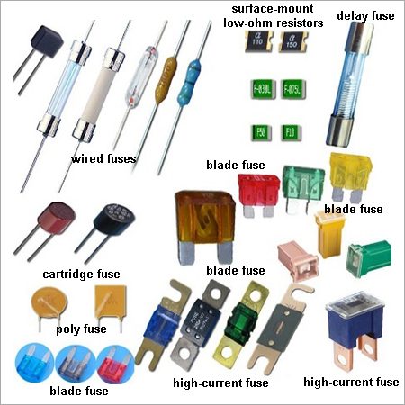
DIFFERENT TYPES OF FUSES


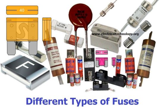
These images show 5 in-line fuse holders,
then panel-mount fuse holders and fuse clips at the bottom


These images show blade fuses

Low-ohm surface-mount resistors can be used as a fuse because the current flowing through the resistor will create heat. The amount of heat is a product (multiplication) of the current flowing and the value of resistance. Basically you can say the wattage dissipated is four times greater when the current doubles. That's why it heats up and fails.
But there is a voltage drop across the resistor AT ALL TIMES and you must take this voltage drop into account when designing the project.
There is no voltage drop across a "normal" (wire) fuse.

                                   to Index
POLY SWITCH
Designing and testing circuits up to 1 amp has very few problems.
Most parts carrying 1 amp do not get very hot and the wiring can be light duty cable.
When the current is greater than 2 amp, you need to take additional precautions because the power supply you are using will deliver a high current and there is a high current flowing most of the time.
If you are using a power supply with current-limiting, use this feature, but if you are using a 12v battery, up to 100 amp can flow if a short-circuit is created. This will burn the leads and even the tracks on a  PC board.
I am very careful whenever I use a 12v battery because two wires touching will burn out all the wiring.
There is a simple way to protect everything. It is called a  FUSE.
It is the cheapest and best item.
You can use a 1amp, 2 amp or 3.15amp fuses
You can also use a circuit breaker.
You can find a 10 amp circuit breaker in a damaged power board. Just pull the power board apart and re-use the circuit breaker.
Finally you can use a POLY SWITCH.
This is a crystalline structure that has a very low resistance (something like 0.05 ohms). When a current flows through the structure it gets slightly warm.   When a higher current flows, it gets slightly warmer and its resistance increases.
This causes more heat to be produced (by the structure) and it gets hotter and hotter. Within a very short period of time its resistance is very high and only a very small current flows.
This current is called "Leakage Current" and can be from 20mA to 100mA.
The voltage of the supply and the leakage current will create heat in the device to keep it in a state of high resistance.
A Poly Switch can take from 10mS to 10 seconds to activate (respond) and this depends on the voltage of the supply and the short-circuit current (the voltage of the supply has an effect on the maximum current flowing).
You need to remove the supply and wait a few seconds for the Poly Switch to cool down.
But there is one more thing to remember about a Poly Switch. It also has a VOLTAGE RATING.
When the Poly Switch "goes open" the voltage of the supply will effectively be across the device and if it is rated for 30v and the supply is 100v, the device will breakdown due to the overvoltage and it will either leak more current or breakdown completely and deliver a lot more current to the "short." 
Understanding how this device works needs a lot more understanding than first meets the eye and is actually a "final year" component consideration as you would need to buy a number of different types and work out which is the most suitable.
In most cases the current-rating of the device (say 1 amp) is the normal current for the device and it will go open when twice this current ( 2 amps) flows.  You have to decide if the "trip current" will protect the product you are designing.  
All the protection devices mentioned above will prevent the leads burning out but nothing will protect any of the electronic components from being damaged.

Here are 3 ways to protect your project from going "up in smoke!" 

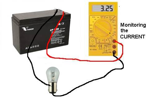
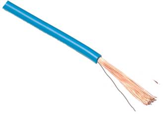
You can make your own fuse by taking one strand of wire from multi-strand hook-up flex and use it to touch the positive terminal of the battery.  If it "goes up in smoke," the circuit is taking too much current.


                                   to Index
EXPERIMENTING
When building and designing circuits, you will find a BREADBOARD is a very good platform for building the circuit. It consists of many holes that are joined under the board with springy metal strips that grip the end of the leads and join them to the other components.
You will learn where the strips are placed under the board from diagrams on the web and the long strips that run from one end of the board to the other are called BUSES.
Sometimes these are cut in the centre and you have to join them with JUMPERS.
These buses allow the POWER RAILS to be available for the whole length of the board and they are sometimes marked with a red line and black line.
You can also get a POWER MODULE that clips onto the end of the board and it will deliver 5v and/or 3v3 to the POWER RAILS.
The following two images show the POWER MODULE and one fitted to a breadboard.

You need to select the voltage for each rail with a tiny jumper (supplied with the module). You can have 5v at the top and 3v3 at the bottom.
 The 5v USB connector is for powering an external device. Do not attempt to use it to power the module. Each voltage will supply up to 500mA.
Before you connect a power supply to your circuit, it is very wise to use a supply made from AA cells. This will deliver a very smooth voltage and if the cells are not new, the current will be limited and the components will not get destroyed, if a fault is present. It will also prove your circuit will work on a slightly lower voltage.

                                   to Index
THE HEAT SINK
Every electronic component get warn or hot when operating.
That's because no component is 100% efficient.
The final temperature of a component depends on how fast the heat can be removed.
This is a very complex problem and even 100 pages of discussion will not deliver a solution.
But the answer is very simple.
Feel every component after 10 minutes of operation and if you cannot hold it for 10 seconds, it is getting too hot.
It's that simple.
Once you have located the components, look on the web and see how other designers have solved the problem.
It may be as simple as increasing the width of the tracks on the PC boar or soldering a small fin to each lead of screwing a heat fin to the component.
WE can provide a whole list of heat fins and the wattage they will dissipate, but most of these fins will not be available in your area, so you will have to do your own experimenting.
I have a drawer of different heat fins and I select one that I know from past experience, will be suitable.
I think of them as SMALL, MEDIUM and LARGE.
Sometimes you will need mica insulation washers and sometimes heat conducting paste.
This all adds to the expense.
If you have a transistor on a large heat sink getting very hot, it may be time to redesign the circuit. This was the case with the video driver transistor on early TV sets. It got very hot an constantly failed. The next design used a tiny plastic transistor with no heatsink and remained cold.
It all rests with the skill of the design-engineer.
You can make your own heat sink from a metal can or piece of aluminium or brass and screw it to the component.
My point is this: Don't waste time calculating the losses.
Simply fit a home-made heatsink and feel the component.
Make sure it does not touch anything. 
You will very-soon work out what makes a good heat-sink.   

WHY DO DIODES AND ZENER DIODES GET TOO HOT?
Sometimes, diodes and zener diodes get very hot.
Why?
There are 3 reasons.
1. The voltage across a diode will be 0.7v when it is passing about 50% of its rated current. When the current rises to 100%, the voltage across the diode will rise to 1.1v or 1.2v. This means the wattage being dissipated by the diode is actually double and it can get very hot.
2. The manufacturer expects the leads to remove the heat and the leads must be connected to very wide PC tracks to remove the heat. If the tracks are too narrow, the diode will over-heat.
3. If the leads on the diode are too long, it will get very hot.
The same applies to zener diodes.
The manufacturer expects the leads will be soldered to very wide tracks as the zener itself will not dissipate any of the wattage.
Make sure other diodes are not nearby or share the same track as this will reduce the ability of the track to remove the heat. 
                                   to Index
HANDY HINT #1:
 
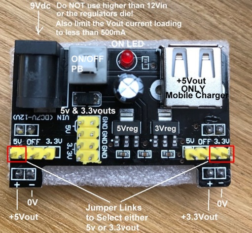
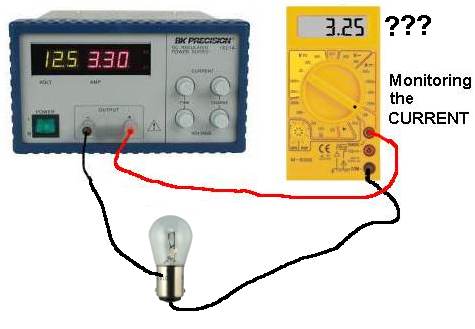
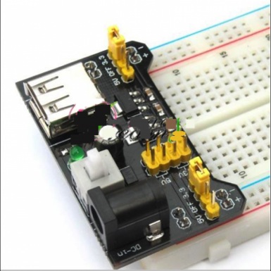
Here's a cheap way to protect your project from damage when testing it for the first time.
If you don't have any low value resistors of 1 watt to 3 watt rating, you can use a very old AA (dry cell) in series with the positive lead.
It will add a small voltage to the output, but it will also LIMIT THE CURRENT and prevent your project being damaged.
The actual current will depend on the age of the cell and a very old cell will be ideal as it will limit the current to as little as 100mA.
It may get charged in the reverse direction during its use and it may get warm or hot, depending on the fault in your project, but you can throw it away after use, rather than throwing away your project.
                                   to Index
PROBLEM 1:

If your project contains a globe (such as on the output) you cannot use a Power Supply with CURRENT MONITORING.
A globe takes up to 6 times more current to start to turn ON (because the filament is cold and has a LOW resistance) and the Power Supply will see this as a LOAD and reduce the voltage. The voltage may be so LOW that the rest of the circuit does not work and this will create a problem. You will think the circuit is FAULTY. Some Power Supplies have a LED to indicate it has gone into CURRENT-LIMIT MODE. In the example above, the globe is 36watt and takes 3 amp when illuminated. But it takes over 10 amp to start to illuminate and the supply has only a 5 amp rating.
The Multimeter is indicating 3.25 amp but the globe is not illuminating. The Supply has "shut down" to less than 4v because the CURRENT LIMITING circuit has reduced the output current to 3 amp and the only way to deliver 3 amp is to reduce the voltage to about 4v. 
The CURRENT MONITOR (current limiting circuit) cannot be turned off and this supply is not suitable. 
                                   to Index

You need a HIGH CURRENT SUPPLY to test a car globe.
                                   to Index
PROBLEM 2:

A power supply is set to 12v.  It is a 0-30v power supply with a maximum current of 5amps as shown on the front of the supply.
When the load is connected, the output voltage drops to 7.6v   Why?

The load is OVERLOADING the power supply.
It is protecting itself.
It can only deliver a maximum of 5 amps.
As the voltage produced by the power supply increases from 0v, the current through the load also increases and when the voltage reaches 7.6v, the maximum of 5 amps flows through the load.
At this point the voltage does not rise any further.
The load connected to the power supply will take 7.8amps (if it is a resistive load) when the supply voltage is 12v and this is more than the power supply will deliver.

THE SOLUTION:
1. Use a 10 amp power supply, or
2. Use a 12v rechargeable battery and a multimeter with 10 amp capability, as shown in the diagram above.

                                   to Index
PROBLEM 3:
A reader in an electronics forum has built an amplifier but its output is very low because he has used a small transformer.
He asks: "Is it possible to hook two transformers together for a higher current?"
We are assuming he means IN PARALLEL.  If they are connected IN SERIES, the output voltage will be too high for the amplifier. 
Normally, parallel connection is not done because two transformers have to be IDENTICAL in the voltage they produce, so they share the load.
If the voltage is not the same, the transformer with the higher voltage will deliver most of the current.
Here is a circuit to connect two transformers and see if the amplifier produces a higher output:
If the transformers have AC output, they must be connected in parallel via a diode on one of the leads FOR EACH TRANSFORMER:
This is only a TEST SET-UP to determine if connecting the two transformers will improve the output of the amplifier. 


                                   to Index