100 more
Crystal Set plans
More good
Crystal Sets
|
41,000 people have read this article in the past 6 years
and many have gained a lot from it as it has the best description
and information, you will find anywhere.
You can even make a crystal set out of kitchen items and a few (easy to get)
components.
It is not until you actually make a "radio" yourself, will you appreciate
the fun of listening to something that was experienced 100 years ago.
|
Everyone wants to make a RADIO. The fun of getting sound from a few
components cannot be bettered.
The simplest radio
is a CRYSTAL SET. (Sometimes called a Crystal-Set Radio or
Xtal Radio Set or Crystal Diode Radio.)
However a Crystal Set needs a number of components that are very hard
to get: (tuning capacitor with knob) and (crystal earpiece for $1.25).
The "air" TUNING CAPACITOR (20p to 415p) is not easily available and
the postage is expensive. The germanium diode is a special component
and the aerial coil wound on a ferrite slab is difficult to obtain.
But you don't need these components. They can be substituted.
There are hundreds of websites on the internet describing the CRYSTAL SET
and if you want to build a "normal" set, you can Google these sites
or
100 more
Crystal Set plans. Many of
them sell kits too.
But this article is different.
We are going to have all the fun of making a CRYSTAL SET but with modern
components and easy-to-make components and with an amplifier stage. The output is loud
so you don't
need a long antenna. And we are going to make our own TUNING CAPACITOR and a
very simple aerial coil (called a FRAME AERIAL) as well as replacements
for the germanium diode (use a TRF radio IC or a transistor) and in place of hi-impedance headphones
(use a piezo diaphragm) and a crystal earpiece equivalent (a piezo
diaphragm).
It's even better to have one of each type of component so you can compare the
performance, so no matter how many parts your get, nothing will be wasted.
We are also going to explain the fundaments
of how the circuit works as even the simplest circuit has a number of very
important features that are used in many other circuits.
But first we are going to learn about the components and how they combine to
make the circuit work.
When two or more components are connected together they sometimes produce a completely
different result to the capabilities of either item.
This is the case with a capacitor and inductor in parallel. An inductor is
simply a coil - turns of wire on a cardboard tube - called a former and the
centre of the coil is AIR. It is called an air-cored coil or air-cored
inductor.
Each component
(the coil and capacitor) is called a PASSIVE DEVICE - in other words it does not amplify, but when
they are connected together they create a result very near to amplification.
And they also produce a result of picking up a huge number of signals and
only allowing one signal to appear across the pair. A truly amazing result.
We start by placing a capacitor across the coil.
There is so much activity in the air, from radio, TV, taxi and mobile phone
usage that the air is filled with electromagnetic radiation.
This radiation will cut the turns of the inductor (the coil) and produce a microscopic
voltage in the turns. This is enough to start the two components passing
energy back and forth at a rate determined by their values. This is
the basis of our first discussion.
These two components are called a
TUNED CIRCUIT and make up our first building block called THE FRONT END.
HOW "THE FRONT END" WORKS
The Front End is the coil and tuning Capacitor. These two items form a TUNED
CIRCUIT in which they pass energy back and forth and produce a waveform with
a very clean natural sinewave shape.
And provided the pair are delivered a little bit of
energy at the right time, they will continue to produce this wave.
That's exactly what happens with the coil and capacitor in a Crystal Set.
They produce a sinewave and the radio station simply supplies energy at the
right time to continue the process.
The actual operation and working of the front end of a radio or crystal set
has never been covered or discussed and so the following discussion has been generated to solve the question: How does a 50 microvolt signal
from radio station deliver enough energy to drive a crystal earpiece?
So, here's the explanation to this
phenomenon:
The radio spectrum is filled with a mass of signals and many of them are
rising and falling and cancelling each other out but some are producing
peaks. The antenna delivers this mass of signals to the coil and it produces
magnetic flux in its turns and a voltage across its ends that is delivered
to the capacitor.
The capacitor simply charges and when the peak has been received the voltage
on the capacitor is higher than the voltage produced by the coil and it
starts to discharge its energy into the coil. This takes time because the
coil produces a back voltage and makes it difficult for the capacitor to
deliver its energy. But eventually it does. If this energy is returned at a
time when the amplitude of the mass of signals is high, the result will be a
higher waveform and the capacitor will be charged a little more. The
capacitor will return this amplitude to the coil and the capacitor will
gradually get charged more and more.
If the setting of the capacitor is at a location on the radio dial where a
radio station is located, the capacitor will charge more and more until it
gets fully charged.
This is because the energy from the radio station produces a signal (energy)
at exactly the time in the cycle to add energy to the capacitor. This may
take 1,000 cycles or more but eventually the capacitor is filled completely.
At this point the capacitor has the maximum amount of energy and it takes a
certain amount of time for the coil to accept this energy because when a
voltage is delivered to the coil it produces magnetic flux that is called
EXPANDING FLUX that cuts all the turns of the coil to produce a back voltage
from of the coil. It makes it very difficult and slow for the capacitor to
deliver its energy but eventually it produces a peak amount of flux. When
the capacitor can no longer maintain this flux, the flux starts to collapse
and cut all the turns of the coil and produce a voltage out the end that is
opposite to before. There are also signals coming from the other radio
stations but the amplitude of these signals is very small compared to the
signal we have now produced and most of the signals are fighting each other
and cancelling each other out.
However there is one signal that is arriving at the exact right time to add
a little energy to that supplied by the capacitor and on the next part of
the cycle it delivers too much energy to the capacitor and it is over
charged and the excess is wasted. This means the capacitor and coil are
transferring energy back and forth to produce the amplitude at a rate
determined by the energy in the capacitor and the time it is being delivered
and accepted by the coil.
At this point in time we have a constant waveform (constant frequency) with
a constant height.
This is the instant when the TUNED CIRCUIT (the FRONT-END) "locks onto" the
same frequency of the radio station.
On the next cycle, the amplitude of the wave is not as high and thus the
coil does not produce the same amount of flux and the capacitor is not
completely filled. However this energy is delivered to the coil and the
radio station delivers a little bit of energy at the right time but the
amplitude is not as high.
The amplitude keeps falling and then rising over about another 1,000 cycles
and this rise and fall represents the audio waveform of the music or speech
being transmitted by the station.
In other words the user selects a position on the radio dial where the noise
and energy from all the radio stations produce a waveform and the peak of a
radio station happens to be at the right location to add to the waveform
generated by the TUNED CIRCUIT. And it adds to the amplitude and fills the
capacitor to a maximum to "lock onto" the station. The coil and capacitor
generate this "fixed frequency" by being completely filled and this starts
the beginning of the "connection." The frequency of the radio stations have
nothing to do with this part of the generating of the frequency. The coil
and capacitor produce the frequency and if a radio station is on the same
frequency, it is "detected."
You have to tune (turn) the capacitor to a point on the radio spectrum where
the signal will always be adding to the energy to charge the capacitor to a
maximum. This is how a 50 microvolt signal will eventually produce a 1 to 2
volt waveform. And although this is a magnification of over 1,000 the
background noise will also contribute to this gain. This gain is called the
"Q" of the circuit and when the amplitude is more than 500mV, a little bit
of the extra height of the signal is able to be "fed off" to the earpiece
via the diode. The negative parts of the waveform do not pass through the
diode and are kept by the inductor to produce magnetic flux in the opposite
direction to improve the positive part of the waveform, later in the cycle.
But to get just one radio station, you must not LOAD the TUNED CIRCUIT.
If you load the tuned circuit, you will not allow the capacitor to fully
charge and it will not get to the point of delivering its energy on an exact
location on the radio spectrum and you will allow signals either side of the
desired signal to charge the capacitor and produce a wider (more distorted
wave) that will allow you to hear two or more stations at the same time.
It is only when the capacitor fully charges that the frequency is SET. And
from there it will deal with a rise and fall in amplitude.
But, loading the tuned circuit reduces the sensitivity and selectivity of
the Crystal Set.
The signals from a radio station are AMPLITUDE MODULATED signals and that is where we get
the name AM RADIO.
The TUNED CIRCUIT can also be called a FILTER with a very narrow BAND-PASS
frequency but our explanation above describes the operation much more
clearly.
Here are a few other terms used to describe
the components in the font end:
LOOP STICK ANTENNA -This is an alternate name given to the coil
of wire wound on a ferrite rod or slab. It also has the name ROD ANTENNA or
FERRITE ROD ANTENNA.
The winding can be enamelled wire or flexible wire called LITZ WIRE. This is
very fine strands of enamelled wire twisted together and covered in
cotton. The purpose of changing a thick wire to lots of very thin wires is
to prevent the radio signals creating loops of signals within the wire and
these signals will cancel each other and not produce a signal out the end
of the wire.
In our experiments, we have not noticed any difference in a coil made with
ordinary enamelled wire and Litz wire.
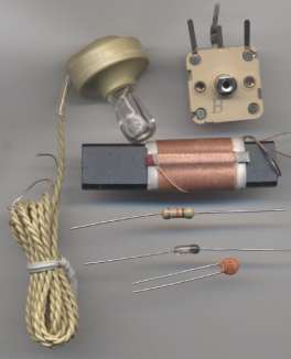
Here is a set of components to make your own
Crystal set from Scott's Electronic Parts:
You can see the rod antenna, germanium diode, crystal earpiece, capacitor
and resistor. The kit costs about $9.00 plus postage and includes knob,
clips and screws but no board to mount the parts.
Here is the circuit for a Crystal Set:
You can try connecting the aerial to different parts of the coil because it
will have different effects.
The aerial both helps and hinders the ability of the Crystal Set to perform.
Although it delivers a signal, it also has a "LOADING EFFECT" because the
Crystal Set is trying to produce a signal that is higher in amplitude than
the incoming frequency.
When we tap the coil at the "earthy end" we produce two "sections" with the
lower section feeding the top section via magnetic flux and allowing the top
section to produce a large waveform. Only the top part of the coil and
capacitor form the tuned circuit.
Here are the components mounted on a board called BREADBOARD:
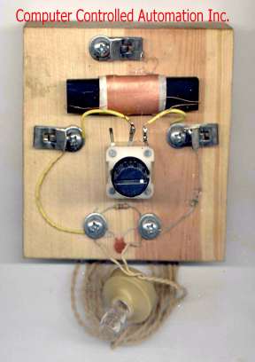
The top clip connects to a long antenna. The left clip
connects to ground and the right clip connects to a short antenna.
Let me clear up a point. You do not need a
ferrite rod antenna for the coil. You can use an ordinary coil wound on a
cardboard tube and it will work just as well if you are using an outside
antenna.
Here is the circuit using a home-made coil.
The tappings on the coil allow a wide band of
radio stations to be tuned.
Each tapping allows a different portion of the band to be covered.
The coil has been worked out to be about 70mm diameter with 0.25 mm
enamelled wire and 80 turns. This requires about 20m of wire.
The next part to understand is this:
The coil and capacitor must not be LOADED. In other words, you cannot
connect anything to this combination because the signal it is producing will
be "taken away" or "removed" or "considerably reduced" by the item you are connecting to the circuit.
These two components are called a TUNED CIRCUIT and when they are not loaded
they pick up all the radio stations and only one station will appear from
the coil when the natural
resonant frequency of the coil and capacitor exactly match the frequency of
the radio station. The circuit actually "rejects" all the
radio stations except one. Because all the other stations are trying to make
the Tuned Circuit oscillate at a different frequency.
The result of the TUNED CIRCUIT oscillating under NO LOAD conditions
produces a waveform that is very high and this gives the circuit GOOD SELECTIVITY. The
circuit can select one station and reject nearby stations.
It also has good SENSITIVITY as it can pick up weak stations.
If you load the circuit, only the strongest signal will be detected and it
will be spread across the full range of the tuning capacitor.
Obviously the theory is more-complex but we are explaining the end-result.
Theory talks about the "Q" value of the coil and this is its ability to
produce a very good output. The "Q" value increases when the circuit is not loaded. .
Although these voltages are very small (in the order of microvolts or
millivolts) the result is very important as the rest of the circuit will be
amplifying this waveform a few thousand times.
As we explained above, pushing the weight on a string only needs a push of 1
cm and eventually the weight will swing 1 metre. This is a gain of
100:1 The same thing happens with the tuned circuit. The incoming radio
signal is in the order of microvolts, but the coil and capacitor will
produce a signal as high as 500 millivolts. This is an improvement or "gain"
of more than 1,000 and is referred to as the "Q" of the circuit.
You will also notice the TUNED CIRCUIT is not connected to any supply
voltage. It
does not have to be connected. It generates its own waveform from the signals
in the air.
It should not have any DC current flowing through it via the supply as this
would put a load on the circuit and reduce its operation.
However we must "pick-off" the signal so it
can be amplified.
This must be done with a very high impedance circuit.
THE CONVERTER (detector) -
THE DIODE
The next part of the circuit is the CONVERTER. Commonly called the DETECTOR.
It converts the RADIO FREQUENCY signal to an AUDIO FREQUENCY signal.
This is the job of the DIODE.
The radio frequency signal is a very high frequency signal (say one million
cycles per second) and it is sending a tone of one thousand cycles per
second through the air-waves.
What is happening is this: The one megahertz signal has a certain
amplitude and over a range of the first one-thousand cycles, the amplitude
gradually decreases and then increases again. If you look at the tops of
this 1,000 cycles you will see a waveform that corresponds to the one
kilo-Hertz signal.
The 1MHz signal is picked up by the coil and
capacitor in the front end and makes it oscillate.
The radio frequency signal is gradually getting larger over 500 cycles then
smaller over the next 500 cycles and this increase and decrease represents
the 1,000 cycles per second tone.
This is the waveform (the signal) that passes through the diode. This
will be explained further in a moment.
The diode does not pass any signals less than 200mV as the first 200mV is
lost in the junction of the diode. This means the signals start to appear
on the other end of the diode when they are above 200mV.
This is how the diode works:
Across the crystal earpiece is a capacitor. The capacitor gets charged via
the diode.
The diode is present to stop the capacitor getting discharged when the
waveform is in the wrong direction. (by this we mean - when the
waveform is lower or smaller in amplitude than the voltage on the
capacitor).
And the waveform is in the wrong direction about 50% of the time. To charge
the capacitor for one-half-cycle requires 500 "little increments" in voltage
with each increment adding a microscopic increase in voltage. We don't want
this voltage to reduce when the waveform is reversing direction and the
diode stops the voltage flowing back to the Tuned Circuit.
During the next half of the cycle when the pulses are getting smaller and
smaller, the voltage on the capacitor is "bled off" by the load resistor.
The crystal earpiece detects this voltage. What we mean, is the diode allows
the voltage to rise (increase) on the capacitor via lots of little "pulses"
and the voltage increases in the form of a sinewave to a maximum amount.
This voltage is passed to the crystal earpiece.
Once the voltage rises to a maximum, the little pulses of energy are not
quite as strong, and the voltage on the capacitor reduces to form the second
portion (quadrant) of the sinewave. This voltage is always being passed to the crystal
earpiece and you can hear it as an audio signal.
GERMANIUM OR SILICON DIODE
The preferred type of diode for a Crystal Set is germanium. This is because
it drops only about 0.3v.
But a silicon diode can be used, even though it drops about 0.7v, if the
radio stations are very loud (close by).
This is the amazing part of the circuit. The signal from a Radio Station is
only a few micro-volts (by the time it travels the distance and reaches your
antenna). But the circuit (consisting of the coil and tuning capacitor) will
keep storing and adding the tiny pulses (of voltage) until the voltage
reaches over 300mV or even up to 700mV and then it will pass through the
diode to your headphones. It is only the voltage above 300mV or 700mV that
you "hear."
You have to remember, you need a very good aerial (and a water-pipe earth)
to get any results with a Crystal Set because you are asking the signal to
provide the energy to drive the earpiece.
By simply adding a transistor, you are improving the performance 100 times
and the long antenna can be reduced to a FRAME ANTENNA and the earth can be
the metal frame of your soldering iron.
THE EARPIECE or EARPHONE
also The Magnetic Earpiece or CRYSTAL EARPIECE
The earphone or earpiece used in a Crystal Set must be a high impedance device because
the crystal set does not produce a high current and cannot drive a
low-impedance earpiece.
That's why a CRYSTAL EARPIECE is ideal.
It has a crystal glued to the back of the earpiece
and connected to its top surface is an aluminium diaphragm. When the crystal
expands and contracts as a result of a voltage applied via two electrodes, the diaphragm moves and you can hear the signal. It exhibits a very high impedance because it consists of a crystal and no
coil of wire is contained inside the case.
If you do not have a Crystal Earpiece, you can make your own from the shell
of an 8 ohm earpiece and a piezo diaphragm. Only the front part of the
earpiece is used.
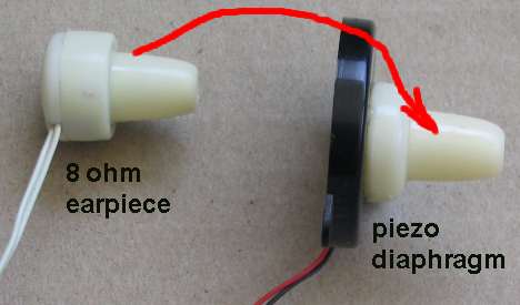
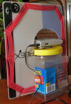
Make your own Crystal Earpiece
Hit the 8 ohm earpiece on the side and the front comes off. Glue the front
onto a piezo diaphragm with hot-melt glue. See photo above.
The piezo diaphragm is a ceramic substrate that deflects in the presence of
a voltage. It is quite sensitive and you can hear the audio quite clearly.
The waveform emerging from the diode in a Crystal Set is called AUDIO and
although it has an amplitude of a few hundred millivolts, it does not have
any current associated with it. The crystal earpiece and the piezo
diaphragm react to this
voltage.
THE 8ohm EARPIECE
The 8 ohm earpiece can be used with our 8ohm Buffer stage
shown below.
16ohm 32 ohm and 64 ohm EARPIECE(s)
Earpieces and headsets from mobile phones are 16 ohm or 32 ohm
per earpiece and are terminated via a stereo 2.5mm or 3.5mm plug. The
earpieces are connected in SERIES to get the best coupling to our radio
circuits and you need to find the two pins on a stereo socket to produce
series connection. Get a multimeter and switch to "ohms." Try all the pins
and you will get a click in the left ear then the right ear. Keep searching
until you get a click in both earpieces at the same time. Use these two pins.

Stereo mobile phone headset - unusually 32R or 64R
PROBLEMS
The biggest problem with a Crystal Set is the need for a long antenna.
The first 200mV to 300mV of a signal is lost in the diode and you need a long antenna
to pick up a signal so the output of the TUNED CIRCUIT has enough voltage to drive
the high-impedance earpiece.
This requires an outside aerial 5 metres long and 3 metres high.
This is not practical for most hobbyists so we will be adding an amplifying
stage to the crystal set so a shorter (smaller) aerial can be used.
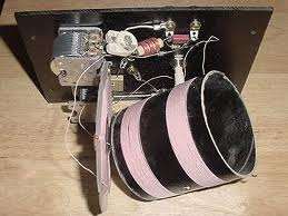
THE FRAME AERIAL or FRAME ANTENNA or
FRAME COIL
The aerial coil shown in the photo above is a ferrite slab with about 80
turns of Litz wire. You can find one of these in an old broken AM radio or
from a parts-shop. In the instructions below we show how to make your own
Ferrite Rod Antenna
An equally-good substitute is a frame antenna made by winding
insulated wire in a rectangle around wooden sticks.
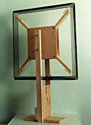
FRAME ANTENNA
15 turns on a diamond frame
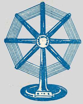
One of the earliest Frame Antennas
The Frame Aerial can be as large as 100cm x 100cm or as small as 10cm x 10cm around a
plastic chocolate box.
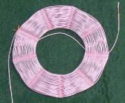
Here are two FRAME ANTENNAS:
This will work just as good as a ferrite slab antenna. The slab antenna is
just 100 times smaller.
The slab
antenna was invented so a transistor radio could be built in a small case.
But if it is not available, you can wind 20 turns around a
plastic chocolate box and it will work just as good.
Alternately you can wind 20 turns around a biscuit tin. Put a pencil on the tin and wind
the turns over the pencil too. Remove the pencil and it will be easy to
remove the turns. Use tape to keep the turns together.
The FRAME AERIAL does two things. It picks up the radio waves and it becomes
the coil (called the INDUCTOR) in the TUNED CIRCUIT. It must be placed away
from metal objects, such as a refrigerator.
BASKET WEAVE COIL
There is no point making a complex BASKET WEAVE
COIL as it will not work any better than simply jumble winding all the turns at the maximum
circumference of the coil, because the energy capturing capability of the coil relies
entirely on the amount of flux lines passing through the centre of the coil.
By increasing the centre of the coil, the amount of flux is increased for
the same coil size.
In fact, the simplest and cheapest is to wind turns around a box, as
explained later in this article, or make a frame antenna as shown above.
Technically speaking, a round coil has the best performance but only by a
few percent.
A BASKET WEAVE COIL
THE VARIABLE INDUCTANCE TUNING COIL
Whenever the size or shape of the coil is changed, (or the number of
turns), the natural
frequency of the Tuned Circuit will change and a different radio station
will be picked up.
This means tuning across the band can be done by altering the
characteristics of the coil while keeping the value of the capacitor fixed.
Changing the inductance can be done in many different ways.
The coil can have taps every 5 turns and an alligator clip selects the
correct tap. But very few radio stations will correspond exactly to each
tap.
Another way is to have a slider move up and down the turns as shown in the
following image:
The slider makes contact where the insulation has been removed. But it may touch two turns
at the same time and create a "shorted turn" and reduce the "Q" of the
coil.
Here is another Crystal Set that did not work:

The copper rod "shorted-out" two turns
Another way is to move a ferrite bar (rod) in and out of the coil:
THE SLUG TUNED COIL
To tune across the radio band, the natural frequency of oscillation of the
TUNED CIRCUIT must be adjusted (changed). This can be done by changing the
value of the capacitor or the value of the inductor.
The value of the inductor can be changed by adding or removing turns or
changing the amount of magnetic material in the centre of the coil.
A ferrite bar can be screwed in and out of the coil or slid in and out and
this component is called a SLUG TUNED COIL.
The following diagram shows a SLUG TUNED CRYSTAL SET:
By changing the value of the 100p capacitor, different parts of the band
can be picked up.
The photo shows a slug tuned coil using 60 turns of insulated wire on a 10mm
tube (or any tube that will fit over a 8-10mm ferrite rod) and a circuit containing an AM radio chip
plus a buffer driver transistor:
A SLUG-TUNED RADIO
The circuit above is has a broad-band amplifier consisting of 10
transistors (IC1) and they are directly coupled (connected) to each other
because it is not possible to "manufacture" a capacitor inside the IC. The
IC has 3 terminals (pins, legs) and it looks like an ordinary transistor.
Experimenting with this type of IC has shown that it is no better than 2
ordinary transistors connected in a direct-coupling arrangement.
Here is the address of the site for the slug-tuned radio.
http://www.kristalradio.nl/
Unfortunately the site is in Dutch and the kit is not available. However the
photos give a clear picture of the how the parts are connected.
The inductance of the coil can also be altered by winding another coil
and placing it near the first coil so that the magnetic field interacts with
each other and changes the inductance of the circuit. This is called a
VARIABLE INDUCTANCE TUNING COIL.
You can have one coil inside the other, two coils near each other or two
flat coils side-by-side. Any two coils will interact with each other.
An Inductive TUNING COIL called a VARIOMETER
MAKING YOUR OWN FERRITE ROD ANTENNA
You can make your own FERRITE ROD ANTENNA by winding 60 to 80 turns of
0.25mm enamelled wire onto a 9mm ferrite rod or slab. If you wind it on a
paper sleeve, you can move the coil along the rod to get the best
performance. When the rod is slid out of the coil, the inductance changes
considerably. However the inductance does change very slightly when the coil
is moved along the rod.
Make your own ferrite antenna
Now we come to the tuning capacitor::
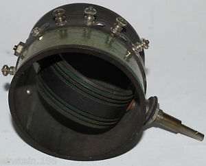
THE TUNING CAPACITOR
The "C" in the "LC" TUNED CIRCUIT can
be fixed or variable. When it is variable, it is called a TUNING
CAPACITOR. The sheets of aluminium in the air tuning capacitor below are called PLATES and the moving plates
are called VANES. The fixed plates make up the STATOR.
The space between the plates is AIR. The photo shows a single capacitor. If
two capacitors are connected to the same shaft it is called a GANGED
CAPACITOR.
The plates do not come fully out of mesh and that's why the capacitor has a
minimum value. The maximum capacitance is when the plates are fully meshed.
The odd shape of the plates is designed to produce a fairly constant increase
in capacitance as the shaft is rotated.
An air tuning capacitor:
Air Tuning Capacitor
(Variable Capacitor)
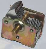
The capacitor can be made much
smaller by using thinner vanes and placing plastic between the vanes.
Plastic increases the capacitance about 3 times to 10 times.
Tuning Capacitor as found in a pocket radio
The tuning capacitor can be replaced with a home-made equivalent that
will work just the same.
You need:
4 sheets of aluminium foil (cooking foil) 10cm x 10cm.
4 sheets of thin cardboard 15cm x 20cm (cut A4 sheets in half).
HOME-MADE CAPACITOR
Tape a sheet of aluminium foil to each sheet of cardboard with sticky-tape
around all 4 sides. Take one strand of wire from a length of hook-up flex
and sticky-tape the end to each sheet of aluminium to make good contact.
Place 2 sheets on top of each other and move the top sheet slightly to the
left and sticky-tape the edge so they don't move. Do this with the
other two sheets but move the top sheet to the right. Now interleave the
sets. Connect the wire from the first sheet to the third sheet.
Connect the wire from the second sheet to the fourth sheet.
The cardboard (or paper) between the aluminium sheets increases the
capacitance three times.
The capacitance decreases when the sheets are moved apart and the
capacitance increases when the sheets are moved in. The capacitance also
INCREASES when the sheets are squashed together such as when a book is
placed on them.
You can also make a smaller capacitor by making each sheet smaller and
using 6 sheets. You can then add a 100p or 220p in parallel with the
home-made capacitor, to select
the lower part of the band.
THE COIL
The coil can be any size and have any number of turns. If it is
70mm diameter with 0.25mm wire and 80 turns it will have an inductance
of about 200uH and with a tuning capacitor of 365p, you will be able to
go down to the lowest frequency of 540kHz.
If the coil has less turns or a smaller diameter you will not get down
to this lowest frequency.
That is why it is suggested to buy a ferrite rod antenna as it will be
smaller. It will not be any more efficient or better but smaller.
Alternatively you can make a FRAME ANTENNA (shown below) that will act
as both an antenna and a tuning coil AT THE SAME TIME. It may not be
good enough to hear a radio station but adding a transistor stage (or 2
stages), will make it 100 times louder and quite portable.
EACH CIRCUIT
Each circuit we describe in the following set of circuits is an improvement or advancement on the
previous. We also offer a number of different
types of aerial coils, amplifying stages and earphones. Some of the
circuits use easy-to-obtain components and home-made equivalents for
hard-to-get items. There will be something in this section for everyone
to build.
In all radio circuits you will encounter TWO MAIN PROBLEMS:
If the FRONT END (the Coil and Capacitor) is loaded too much by the
"pick-off" of the amplifying stages, you will only get one station.
If you get squealing or "motor-boating," try a different circuit and
layout as the components you are using, plus the voltage of the battery,
will need changing.
You cannot always increase the voltage of the supply and get a louder
output. Sometimes the increased voltage will stop the circuit working or
it may introduce too much gain that the circuit starts to squeal.
The Radio IC (ZN414) DOES NOT WORK on a voltage above 1.5v and some of
the transistor circuits completely stop working with a higher voltage.
This has to do with the biasing arrangements and if the circuit is
designed for a low voltage, you need to keep to the suggested voltage
and experiment with a slight increase in voltage and see what happens.
Building a radio is not easy as the enormous amount of amplification of
the combined stages creates a feedback loop via the power rail that sets
the circuit into oscillation. This effect gets worse with a higher
supply voltage and we will explain this further with each of the
circuits.
MAKING A CRYSTAL SET
You can buy a CRYSTAL SET kit (see the photo of the kit, above) or the individual components (a kit
is the cheapest) or use the replacement for the FERRITE ANTENNA COIL
(16 turns to 20 turns on a 150mm biscuit tin) and/or the TUNING
CAPACITOR made from aluminium foil and cardboard sheets.
You will need an outside antenna and an earth (such as a water tap or the
frame of your soldering iron) to pick up the radio stations.
If you cannot put up an outside antenna, you will need to add one or
more amplifying stages and this will allow you to reduce the length of
the antenna and increase the volume of the audio.
ADDING AMPLIFYING
STAGES TO A
CRYSTAL SET
You can add two different types of amplifying stages to a crystal set.
You can connect amplifying stage(s) to the FRONT END and these
will be designed to put less load on the front end so the sensitivity
and selectivity increases. These stages work at the frequency of the
radio signal and they are called RF STAGES (Radio Frequency Stages).
You can build these stages out of individual components or use a
chip called a RADIO CHIP or RADIO IC (integrated circuit) for less
than $2.00.
The chip contains 5 stages of amplification and these are RF stages (or
RF AMPLIFYING STAGES) and the concept is called TRF. (Tuned Radio
Frequency).
It is not easy to get this type of amplifier working because the stages
produce a very high overall gain and you get a lot of "motor-boating"
and squealing if the gain is not controlled. The gain must be reduced
when a strong signal is being passed through the circuit because a
strong signal will produce a large output and this will be so large that
some of the waveform will find its way to the front of the amplifier via
the power rail and
start to be amplified again. To prevent the output getting too large,
the circuit has a negative feedback line - called the AGC line -
Automatic Gain Control.
It would be very difficult to reproduce these 5 stages of amplification
with discreet components and that's why it is best to use an IC.
The next stage is a DIODE to convert the RF (Radio Frequency) to AF
(Audio Frequency). This can be done with the diode-characteristics of a
base-emitter junction in a transistor and we will show the alternatives.
Any stages after the diode are AUDIO STAGES or AUDIO AMPLIFIER STAGES.
The main job of the AUDIO AMPLIFIER is to increase the DRIVE CAPABILITY.
In other words, increase the current capability of the circuit for an 8
ohm speaker or 8ohm earpiece (or 16 or 32 ohm).
This is a very difficult thing to do and requires at least 2 stages.
The LOAD you can put on a Crystal Set must be 10,000 ohms or higher. (if
you put a lower resistance (impedance) on the output, you will load the
FRONT END and reduce its ability to separate the stations.
That's why a crystal earpiece is normally used with a crystal set. It
puts almost NO LOAD on the circuit.
If you put a load on the circuit the result will be only one or two
stations across the whole dial and only the most powerful station will
be received.
If you don't have a crystal earpiece, you will have to use an 8 ohm
earpiece. This will require an IMPEDANCE CONVERTING CIRCUIT of 1,250:1
This is a simple way of saying we want the 8 ohm earpiece to appear as
10,000 ohms to the crystal set.
To produce an overall gain of 1250, we need two stages of amplification.
If a transistor has a gain of 70, it will it will produce an impedance
conversion of 70 times. This is a realistic value. Transistors with a
gain of 200 will have a gain of about 70 when fitted to a circuit. This means the other
transistor needs to have a gain of about 20 and that is easy to achieve.
ADDING AMPLIFYING
STAGES TO THE
FRONT OF A
CRYSTAL SET
Adding stages to the front of a crystal set are called RF STAGES
(Radio Frequency Stages) because they amplify the RADIO STATION SIGNAL.
It does not matter if you amplify RF signals or AF signals. The result is
the same.
The only difference is this: The frequency of RF signals is much higher
(1,000 times higher) and the coupling capacitors can be much smaller.
This allows an RF amplifier to be built into an IC - called a Radio Chip.
One of the most popular Radio IC's is ZN414 or YS414. This chip has been
copied by other manufacturers as: MK484, TA7642 and LMF501T.
All the chips are the same but the pinout is different.
These chips work on a 1.5v supply and if the voltage is increased above
1.5v, the gain of the stages increases to a point of total distortion.
To prevent strong signals producing distortion on 1.5v supply, the output is
passed back to the input via a 150k resistor. This feedback line is called
the AGC (Automatic Gain Control).
The chip contains 5 stages of amplification plus a stage that converts the
RF signal to AF (Detector Stage).
This means the signal diode in a Crystal Set is not needed.
Here is the circuit of the TA7642 Radio Chip. It performs the same as the
ZN414 Radio Chip.
Here is the BLOCK DIAGRAM of the ZN414 Radio Chip:
The ZN414 chip can be purchased from Talking Electronics for $1.00 plus
postage
USING THE ZN414 RADIO IC
By using the ZN414 radio IC (or any if the equivalents) you can create a
POCKET RADIO to drive a headphone or speaker.
But it is not easy to use the chip. The main problem is receiving the strong
signals without producing distortion and then being able to pick up the weak
stations.
A fixed 100k feedback resistor does not provide adequate control and a TRF
radio has limited capabilities.
That's why radio manufacturers make SUPERHETRODYNE receivers. Even though
they are more complex, the result is far superior.
However a simple TRF set can be made with the Radio IC and a few stages of
audio amplification.
The following circuit uses just the Radio IC and a crystal earpiece or the
home-made earpiece described above:
You can use a home-made FRAME ANTENNA or a home-made FERRITE ROD
ANTENNA and a home-made VARIABLE CAPACITOR.
The Simplest ZN414 Radio
Connecting the ground (0v rail) to the frame of your soldering iron or a
water tap will increase the output volume. The circuit above shows a
Crystal Earpiece. Using a Crystal Earpiece may require adding a 10n across
the earpiece to improve the output volume. The substitute Piezo Earpiece is
effectively a 20n capacitor and an additional capacitor is not needed.
2 TRANSISTOR RADIO
Here is a simple 2-Transistor radio.
The secret to its performance is the 7 turn "pick-off" from the FRONT END
(the TUNED CIRCUIT).
The ratio of 7 turns to 60 turns means a small percentage of the
voltage generated in the tuned circuit is passed to the transistor.
Thus it puts a
small load on the TUNED CIRCUIT.
I don't want to go into any mathematics. The turns ratio is 60:7 = 8 but the
effect of the 7 turns "pick-off" has an effect called the IMPEDANCE
EFFECT and this is the SQUARE OF THE TURNS RATIO. Thus the IMPEDANCE
EFFECT is 8 x 8 = 64. This means the "pick-off" (the LOADING EFFECT)
is just a few percent. The front end can produce voltages as high as 500mV
because a crystal set can produce a voltage high enough to pass through a
diode (350mV) and have sufficient to drive a crystal earpiece.
Even though the front end has a "step-down" ratio, the voltage out the 7
turns will be sufficient to drive the first transistor.
The "transformer" does 2 things: It reduces the loading on the tuned circuit
ENORMOUSLY and it produces an output with a higher current than is
circuiting in the front end. Even though the transistor is turned ON and
biased by the 33k, it is classified as a low-impedance load as far as the
front end is concerned and the input signal has to be accompanied by a
certain amount of current, otherwise the transistor will not respond to the
voltage. The 7-turn "pick-off" is able to provide this current.
Both transistors are biased ON via the 33k base-bias resistors and thus the
first transistor responds to the slightest millivolt signal.
This circuit was tested and had the same performance as the Simplest ZN414
Radio Circuit above. It can be operated on 1.5v to 6v and the strongest
stations tend to overload on 6v. A short antenna is
needed.
SIMPLEST 2-TRANSISTOR RADIO
using a very-high-impedance earpiece
SIMPLEST 2-TRANSISTOR RADIO
using a crystal earpiece
ADDING AN IMPEDANCE MATCHING STAGE
You can add an IMPEDANCE MATCHING STAGE to the output of the circuit above
so a low-impedance earpiece can be used.
We call it an IMPEDANCE MATCHING STAGE because this is the correct technical
term. It is an AMPLIFYING stage but it amplifies the CURRENT because the
second transistor cannot drive an 8 ohm LOAD. 8 ohms is a very low
resistance and if it is connected directly to the second transistor, the
output will be almost zero.
The reason for this is covered in our discussion:
The
Transistor Amplifier.
This stage will not increase the volume but simply match the 8 ohm load to
the circuit above.
It is very difficult to connect a LOAD to this type of circuit because it will take more current from the battery and cause the supply voltage to
fluctuate. These fluctuations will be passed to the first stage and cause
variations in the signal. This will be amplified by
the first and second transistors in
the form of a low-frequency buzzing called MOTOR-BOATING.
The only way to reduce or remove this noise is to add an electrolytic
across the power rails and reduce the supply voltage.
The third transistor simply takes the waveform on the output of the second
transistor and delivers it to the earphone with a higher current. It is
called an IMPEDANCE MATCHING STAGE as it effectively increases the 8 ohm
load by a factor of about 100.
3-TRANSISTOR RADIO with buffer stage for 8 ohm earpiece
The 3rd transistor converts the 8R to about 800R
You can use 16 ohm, 32 ohm or 64 ohm in place of the 8R
earpiece and these will give better performance as they will take less
current and improve the stability of the circuit.
Low-impedance earphones create "motor-boating" due to the peaks of current
and this can be very hard to fix.
A 2-TRANSISTOR RADIO with REGENERATION
The next stage in our discussion, to get better performance, is a feature
called REGENERATION.
Regeneration sends a small output signal back to a previous
stage in the form of POSITIVE FEEDBACK to INCREASE the original signal. The
signal on the emitter of the first transistor is the same phase (moving in
the same direction) as the
signal entering the base but the FRAME ANTENNA has a turns ratio of 5:15 and
this increases the signal on the receiving section of the antenna by up to 3
times. But we want the returning signal to be just above the amplitude of
the receiving signal and so a resistive adjustment (attenuator) is provided
on the emitter to deliver just the right amplitude.
This has the effect of increasing the amplitude on the TUNED CIRCUIT and is
just like reducing the load on the circuit.
As we have mentioned above, when the tuned circuit is lightly loaded, it
will pick up a station at the exact frequency of transmission and if the
dial is changed slightly, the station will disappear. This quality is called
SELECTIVITY.
At the same time, the Tuned Circuit will pick up weak stations and this is
called SENSITIVITY.
The quality of a receiver depends on the loading of the TUNED CIRCUIT.
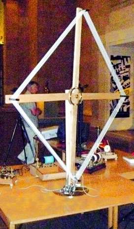
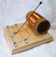
Here is the original circuit from Elektor Magazine with the prototype made
on matrix board and fixed to a base-board with a frame antenna made from two
sticks of wood. The photo shows a speaker but the output is so low that you
absolutely need headphones.
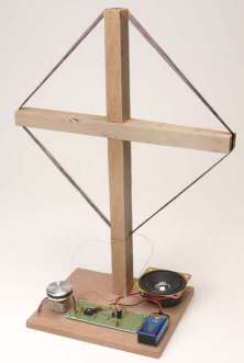
2 TRANSISTOR REGENERATIVE RADIO from Elektor Magazine
The circuit is very complex and the output will be very low as the circuit cannot drive a low-impedance
earphone via a 4k7 load resistor. The 4k7 resistor is actually driving the
speaker (the transistor is simply discharging the 220u). The 4k7 only allows
32/4700 x 9 = 61mV to appear across the earphone - a very poor result.
The skill in designing a transistor stage is covered in our comprehensive
eBook:
The
Transistor Amplifier and you wont make a mistake like this !!!
This output stage is also covered in our section called
SPOT THE MISTAKE Page 26.
(at the end of page 26)
The circuit above can be simplified and we can add the REGENERATIVE feature to
our Simplest 2-Transistor Radio circuit:
Our circuit uses a 15 turn circular FRAME ANTENNA 15cm diameter and a 5
turn REGENERATION coil.
2 TRANSISTOR RADIO with REGENERATION
The regeneration coil is brought near the main coil and as it gets closer
you can hear the audio get louder. If this does not happen, turn the coil
around.
Early radios used this technique and the operator had to adjust the coil by
hand. No-one minded because radio was a fascination and the simplest radio
cost more than a weeks wages. To listen to a broadcast through headphones
was an amazement and listeners would sit all night with headphones listening
to music.
This is very fiddly and by adding an extra buffer stage, we can use a Frame
Antenna with a very clever "pick-off" that does not load the front end
(loads it very little). This
gives the circuit very good sensitivity and selectivity without
regeneration.
3 TRANSISTOR RADIO
Here is our final design for the simplest self-contained
3-Transistor Radio using our home-made Tuning Capacitor and 250mm x 350mm
Frame Antenna. It picks up the local stations and drives a low-impedance
earphone or set of earphones (from a mobile phone).
3-TRANSISTOR RADIO
The circuit performs very well and uses readily-available
components.
The 22n across the output is essential to stop squealing.
The secret to sensitivity and selectivity is the turns-ratio on the Frame
Antenna. The 3-turn "pick-off" puts very little load on the front end and
this allows the stations to be tuned with our home-made Tuning Capacitor.
The circuit contains all the features we have discussed above and only needs
a 1.5v supply.
Build this circuit before you buy any expensive tuning capacitors, IC's or
ferrite slab antennas as you will not get any better results.
This is called a TRF circuit because the stages operate at Radio
Frequency or Audio Frequency. Due to the high amount of amplification, the circuit can start to squeal (feedback, motorboat) due to
the layout.
You may need to shorten or lengthen the leads to the antenna or move the parts slightly - it's that critical.
However the result is a portable radio that needs no earth and will pick up
strong stations.
You can try connecting the 0v rail to the metal part of a soldering iron to
increase the number of stations.
Here is a 2-transistor amplifier from a reader. You can get all his
description by emailing him.
Compare its performance against the 3-transistor circuit above by replacing
the two audio stages with the Headphone Amplifier.
My Comment: You always get the greatest gain when the stages are directly
coupled, but you should experiment and come to your own conclusion.

The Headphone Amplifier built on Matrix Board and fitted into a 2-cell
battery case
LOADING
The whole success of picking up a radio station is the RECEIVING CIRCUIT.
The receiving circuit is the coil and the signal in the air (from the radio
station) must go down the centre of the coil.
It cannot pass over the top or the bottom of the coil. Only the signal that
goes through the centre of the coil is received.
As you can see, the centre of the coil is not very big and it is amazing
that the signal can pass through the centre. But it does, and that is the only
signal that will be amplified.
This signal is passed to the capacitor and we have explained how the signal
is gradually increased and increased in amplitude until it is as large as
500mV.
These two components form a circuit called a TUNED CIRCUIT. It is also
called a RESONANT CIRCUIT because it resonates or oscillates at a
particular frequency.
The signal from the radio station may be as small as a few
millivolts, but as it keeps pushing the "swing" back and forth
(see previous example of a swing in the txt above), the
amplitude gets larger and larger.
If you put your finger on the "swing" you will prevent it getting larger and
larger and it only requires the slightest touch of your finger to prevent
the swing gaining full amplitude.
In electronic terms, your finger is called LOADING THE CIRCUIT and since we
have to pass the signal to further stages of amplification, we need to "tap"
or "load" or "pick-off" a signal.
The aim is to load the circuit as least as possible because the actual
energy entering the circuit is very small.
In fact, this is all the energy we can remove as that is all the energy
entering it.
Because a very small amount of energy is entering the "front-end" we
classify it having a very high impedance. It is very difficult to
provide a value of impedance for this circuit because impedance has the term
"Z" and the circuit is operating a very high frequency so resistance values
are not the same as impedance values.
The actual resistance of the circuit is ONE OHM but the impedance is more
like 10,000 ohms to 100,000 ohms.
We can explain its high impedance if we put a 100,000 ohm resistor across
the circuit. The waveform will be reduced very slightly. If we put a 10,000
ohm resistor across the circuit, the signal will be reduced a reasonably
large amount. If we put 1,000 ohms across the circuit it will stop working.
This means a load of 100,000 ohms will have the least effect.
In a crystal set, the diode creates NO LOAD until a voltage of 350mV is
reached. It then passes excess voltage to a crystal earpiece that has a very
high impedance. That's why a crystal set will produce a good output. The
LOADING is very small.
When a transistor is connected to the TUNED CIRCUIT, it starts to put a load
on the circuit after 600mV and this load is VERY HIGH. The "resistance" of
the base-emitter junction is about 1k and the signal will find it very
difficult to rise above 600mV because the incoming energy is not sufficient
to increase the voltage.
Adding a capacitor between the base and the front end allows the transistor
to be self-biased and get a turn-on voltage of about 600mV from a base-bias
resistor. This allows most of the energy for turning on the transistor to be
supplied by the base-bias resistor and the energy from the tuned circuit can
assist in turning the transistor on and off to produce the audio.
The FRONT END is now separated from the transistor and ANY voltage it is
producing will be passed to the transistor via the capacitor.
The Front End does not produce the 350mV immediately. It takes thousands of
little pushes to gradually increase the voltage, but at 1MHz, this does not
take very long.
Whereas, with the crystal set, the first 350mV could be produced without any
loading, the circuit is now loaded AT ALL TIMES.
This means we have to load the circuit as lightly as possible to be able to
pick up individual stations.
The only way we can do this is to use a capacitor of the smallest practical
value and this has to be worked out by trying different values. If the
value is too small, the transistor will not detect a small signal. If the
value is too large, the circuit will stop working.
Values such as 1n, 10n and 100n are suitable.
Values such as 1u, or 10u will be too large.
Another way to talk about the amazing
properties of the FRONT END is to explain its ability to convert a very weak
(small amplitude signal) as small as 1µV to 5mV into a 500mV signal.
A radio signal loses amplitude as it passes through the air and by the time
it reaches your radio, it is only a few microvolts or millivolts in
amplitude.
All the other signals are "fighting each other" and having no effect on the
FRONT END. The FRONT END is made up of a coil and capacitor and it is also
called a RESONANT CIRCUIT because it resonates (oscillates) at a particular
frequency.
The only signal picked up by the coil (and passed to the capacitor) is the
station we want to hear.
It passes it to the capacitor and the capacitor passes it back to the coil
and the radio signal adds to the amplitude and after a few thousand cycles,
the amplitude is as high as 500mV.
The fact that these two components can produce a high voltage from a very
small energising voltage is due to the constant "pushing" effect of the
signal as it gradually increases the voltage flowing between the two
components and it can convert the 1µV wave into a 500mV signal. The
amplitude is not produced immediately. It takes time (a few thousand cycles)
to build up to a maximum value.
A Crystal Set should be one of the first projects on your list. It was the
first major project I built when I was 12 years old.
I was listening to a radio station and at the same time I had another
crystal earpiece in my other hand and was connecting the leads to various
parts of the crystal set.
All of a sudden I heard noises that were not from the radio station.
I suddenly realised I was listening to sounds in the room and I had made a
very simple amplifier.
This was the beginning of my interest in amplifiers and from there I went on
to flip flop circuits and other digital circuits and eventually to
microprocessor circuits then microcontroller circuits.
But you have to start somewhere and there is no better place to start than
making your own home-brew CRYSTAL SET.
3-2-2019 and 1-6-2020 with Headphone Amplifier circuit 14--7-2022
|
