|
EARWIG |
This kit is designed and manufactured by TALKING ELECTRONICS
For the latest price see: talkingelectronics.com
Download: Earwig.pdf
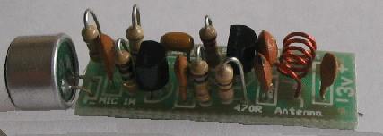
The Complete EARWIG
A bug in a matchbox . . .
Earwig Circuit
This is an easy to build FM transmitter that fits
into a matchbox. It transmits to any standard FM radio and can be used around
the home as a baby minder or outdoors for up to 300 metres. Its sensitivity and
clarity are very impressive -even the ticking of a clock can be picked up 3
metres away.
Almost everyone has the ambition to use the airwaves. Whether it be for remote
control or transmitting halfway around the world, we all love to broadcast.
This project will get you on the air with the least fuss and you can build two
units to achieve a two-way link over a range of 300 metres or so.
We've called the project EARWIG because an earwig is a small bug and so is
this.
The concept of FM transmission is superb. It produces an extremely high quality
signal that is noise-free and it is relatively easy to get a good range with low
power.
The Earwig produces no more than 8-10 milliwatts of radiated signal and yet the
range is quite impressive.
Buildings and high-voltage transmission lines have an effect on the range and
they can sometimes limit the signal to less than 100 metres. But this will be
very rare as the signal finds its way through and around obstructions with very
little trouble.
The most challenging part of this project is to achieve the best range using 1/2
wave antenna and 3v supply.
By constructing the Earwig, you will learn a lot about FM transmission and see
how effective it is.
The first question you may ask is: "How can I increase the range?" The answer is
not as simple as it seems. A lot of complications creep in when the voltage and
power are increased and we must warn you that serious interference may occur to
TV sets when you start increasing the supply voltage.
Everything is quite safe when you are down at 10 milliwatts and although you can
achieve 300 metres, the signal strength at this distance is only a few
microvolts and you are almost down to snow.
These FM transmitter projects are for interest and educational purposes only and
have a magnetic draw about them.
You can spend hundreds of hours experimenting and improving the design and
sometimes you come right back to square one.
We have done all the experimenting for you and come up with the simplest and
best design. It is small enough to fit inside a match box and comes with a 15cm
antenna for inter-room communication.
We have had a unit running for nearly 12 months. It sits on top of the TV during
news and similar programs and the writer has an FM radio next to his typewriter.
He can monitor the TV while typing and if an important item comes up, he can
rush in and watch it.
Mind you, most programs need very little viewing and when the adverts come on,
you can turn the radio down for up to 2 minutes. It's amazing what can be done
in two minutesl
The Earwig can also be used as a baby monitor for those times when you are next
door or in the garden.
It's left in the children's bedroom and if they wake up and start crying, you
can attend to them quickly.
The unit looks a bit like a video sender and you can use any one of a number of
boxes to house the circuit: or, as we have suggested, you can use the humble
matchbox.
The current consumption is less than 5 milliamps and you should get between 80
and 100 hours of operation on two 'N' cells.
The circuit has been designed for maximum output rather than immunity to stray
capacitance and although it has a very low drift factor, it is not possible to
touch the circuit without it drifting off frequency. A 'tight' circuit will be
described in another project as the output has to be kept to a minimum if the
frequency is to be stable when the circuit is handled.
Although the circuit is not crystal locked, the frequency drifts very little in
normal operation and our tests showed a receiver did not need re-tuning after an
8 hour test. The only thing that will influence the output frequency is the
condition of the batteries. As they age, the frequency changes slightly.
A reduction in the transmitting range will indicate the voltage has fallen to
the minimum allowed and the cells should be replaced. They are soldered together
to fit inside the matchbox and provided they are soldered quickly, the seal on
top of each cell will not be damaged and they will not leak.
All the components are easy to obtain and if you know what you are doing, you
can use parts from your own sources. If you have any hesitation about wire size,
coil diameter, identifying a monoblock capacitor, reading 10p or 1n on a ceramic
or the type of electret microphone to use, you should buy a kit.
Kits are available from Talking Electronics as are ALL our projects, and the
complete kit of parts includes a pre-wound coil and PC board with an overlay.
The only item you need to buy is a matchbox and perhaps a few fake matches.
HOW IT WORKS
The circuit consists of two stages, an audio amplifier and an RF
oscillator.
The electret microphone contains a FET transistor and you can count this
as a stage if you wish. The FET amplifies the change in capacitance of
the diaphragm at the front of the microphone and this is why electret
microphones are so sensitive.
The first transistor is the audio amplifier stage and has a gain of 20
to 50 and amplifies the signal for injection into the base of the RF
oscillator stage.
This stage is designed to operate at 88MHz and the frequency is set by
the inductance of the 5-turn coil, together with the 47p capacitor. The
frequency is also determined by the transistor, the 18p feedback
capacitor and also to a lesser extent by the biasing components.
When power is applied, the 1n base capacitor will gradually charge via
the 22k resistor. But the 18p will charge much faster, via the
oscillator coil and the 470R resistor. The 47p will also charge
(although only a very small voltage will appear across it) and the coil
will produce a magnetic flux.
As the base voltage gradually rises, the transistor will turn ON and
effectively put a resistance across the 18p,
A few difficult-to-describe cycles will now occur while the 1 n charges
to the operating voltage of the stage and we will resume our discussion
when this is nearly reached.
The base voltage will continue to rise and the 18p will have the effect
of trying to prevent the emitter from moving. A point in time is reached
when the energy from the capacitor is exhausted and it can no longer
resist the movement of tha emitter. The base-emitter voltage decreases
and turns the transistor off. The current flow in the coil then ceases
and the magnetic flux collapses.
This collapsing magnetic field produces a voltage in the opposite
direction and whereas the collector voltage may have been 2.9v, it will
now rise to over 3v and charge the 47p in the opposite direction. This
voltage will have the effect of charging the 18p and the voltage drop
across the 470R emitter resistor will be such that the transistor will
be turned more firmly OFF.
As the 18p charges, the emitter voltage will drop to a point where the
transistor will begin to turn ON and the current flow through the coil
will oppose the collapsing magnetic field.
The voltage across the coil will reverse and the collector voltage will
drop. This change will be passed on to the emitter via the 18p and the
result will be that the transistor will turn ON very hard and short out
the 18p. After this the cycle begins again.
What we have is an oscillator circuit that produces AC energy at 88MHz
with the amplified audio signal fed into this stage via the 10On varying
the frequency of oscillation to produce the FM signals.
CONSTRUCTION
Before commencing construction it's a good idea to place the two cells
and PC board into the matchbox and see how much room you have. The
headroom is most critical as you need to leave space for a single row of
matches on a thin sheet of card. In fact you can glue a few dead matches
on the card to add more reality.
Lay all the components on the work bench and identify each of them.
There's nothing more annoying than putting two components on the board
incorrectly and having to change them later.
To avoid this, place the parts so that they match the positions on the
board. This will allow you to concentrate on soldering.
The solder we recommend is superfine .71mm resin core type, as thin
solder makes a much neater connection. As one salesman told us "It goes
twice as far!"
A small 15 to 20 watt iron is needed and provided the tip is cleaned on
a wet sponge before starting, you will have no trouble in producing a
first class job.
The only item that needs fabricating is the coil. It can be wound with
.5mm or .71mm enamelled or tinned copper wire.
Although the wire diameter is important, it is not as critical as the
number of turns, the diameter of the coil or its length.
Wind 5 turns on a 3mm diameter shaft such as a medium Philips
screwdriver and space the turns as shown in the photos, over about
5.5mm.
Final setting of the frequency will be done by stretching the turns
apart or squashing them together and at this stage the coil is ready for
fitting. If you have made the coil from enamelled wire, the ends should
be tinned up to the point where they enter the PC board. This tinning is
done while the coil is on the screwdriver to act as a heatsink and any
surplus solder should be removed so that the ends will fit down the
holes in the board.
Now you can wire up the PCB (printed circuit board). Start at the
microphone end of the board but leave the microphone to last to prevent
the leads being damaged when fitting the rest of the parts.
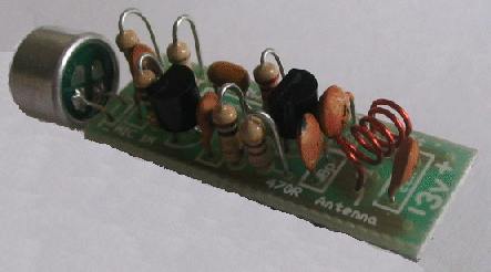
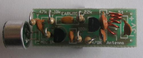
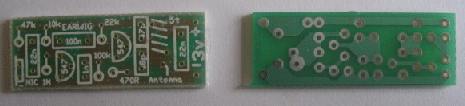
Top and underside of the EARWIG PC board
The resistors stand on end and fit firmly up to the board, to keep the
height to a minimum.
Continue across the board, fitting each part as you come to it. The
transistors should be pushed down so that they are only as high as the
other components. Add everything, including the microphone and finally
the batteries, switch and antenna.
The batteries are soldered together by using the switch and some tinned
copper wire at one end and soldered to the board with a short length of
tinned copper wire from the positive terminal
and hook-up wire from the negative terminal.
Solder 15cm of tinned copper wire to the point marked "A" on the board
and construction is complete.
WHY?
Have you ever wondered why a circuit doesn't work? How many times have
you built a project from a magazine and it doesn't function as
described?
Don't blame yourself or blame the magazine. Most of the time its due to
a factor called tolerance.
As made by the manufacturer, all components have a value falling inside
a "spread range" rather than the nominal value marked on them. The width
of this range is known as the tolerance. So if the tolerance is said to
be 5%, it means the value of a particular part will be anywhere between
5% below and 5% above its marked value.
Tolerance applies to resistors, capacitors, transistors, microphones,
coils integrated circuits and almost anything you can think of.
Then we have another factor called limits. For each component in a
circuit there will be a range of allowable values for that part.
Providing the value remains inside that range, or inside the limit, the
circuit will work properly. Normally each components value is chosen so
that it falls inside this range.
Most circuits are not very critical and for any particular component
they will generally work equally well if we select the next higher or
lower value. If not, the circuit is either very critical or the chosen
value is the most appropriate.
When you place a circuit on the open market, such as in a magazine, you
have an enormous range of potential builders, drawing their supplies
from many different sources. Sometimes they use the designated values
and sometimes they select the next value. Also some components have a
close tolerance while others have a wide tolerance, such as +/- 50% When
the spreads and limits are combined in a random manner, you can quite
often end up with a circuit that doesn't work!
Take the electret microphone for example. On a 3v supply, some
microphones are super-sensitive with a 100k load resistor. Others may
require 4k7 to get a barely acceptable sensitivity. You can not tell the
two apart from the outside. They both look the same. But electronically
they are quite different.
We are talking here of hundreds of percent difference, whereas the
manufacturer's specifications state one has a sensitivity of -22dB and
the other -54dB. In simple terms we can say every
3dB down is twice the sensitivity, making the -54dB unit about 2,000
times more sensitive!
The same can apply to transistors. The specification sheets may show two
devices to be nearly the same and yet when they are connected to a
circuit, one will work perfectly while the other will fail to operate.
This is one of the reasons why the kit market has flourished. Kits are
generally put together from batches of parts that have been tried in the
circuit and for this reason we are advocating first-time constructors
invest in a kit.
You have the greatest potential for success and nothing is more
encouraging than success.
SETTING UP
Once all the components have been soldered in position, the project can
be set up and tested for performance. The test procedure is to add a
short antenna (about 5 - 15cm long) to the antenna point on the board
and tune an FM radio across the band, looking for the signal.
It is best to keep the transmitter some distance from the radio, to
prevent any of the harmonics (side tones) from being picked up.
If you cannot detect the carrier, it may mean the frequency is below the
band. Move the turns of the oscillator coil apart a little and try
again. If you are using tinned copper wire, make sure none of the turns
are touching. If you are using enamelled wire, make sure the coil has
continuity by either measuring it with a multimeter set to low ohms or
measuring the current taken by the circuit, which should be about 4-6mA.
Once the carrier is detected, you can check the sensitivity of the front
end by placing the Earwig near a clock. The ticking should come through
loud and clear and the circuit should be more sensitive than your ear.
The load resistor for the electret microphone (22k) will determine the
sensitivity and it may have to be lowered to 10k or raised to 47k,
depending on the sensitivity required.
Make sure the frequency of transmission is well away from any of your
local FM radio stations as a signal from a station will swamp the Earwig
when you are testing for range.
By moving the turns of the coil together, the frequency will be lowered
and if the turns are spread apart, the frequency will increase. This
saves using a tuning capacitor and keeps the cost down but you can use a
trimmer if you wish.
A word of assistance here. If you use a 5-65p air trimmer, for example,
it will be very difficult to tune the circuit to a
specific frequency as a few puff (picofarads) will change the frequency
by 1 MHz or more. It is better to use a 39p ceramic and put a 4-11p
trimmer across it. This way you are fine tuning the circuit and you have
much more lee-way with adjustment.
Theoretically the inductor should also be adjusted to maintain the L/C
ratio of the tuned circuit, but over the small range we require, this is
not critical.
The output power of the Earwig can be determined by using an FM radio
with a tuning indicator. You really need to have a comparison as 4
divisions on the meter of our tuner indicates a very good output. We
tested the output of our prototype with a 15cm length of antenna laying
horizontally and about 10 metres from the tuner. With 4 divisions we
know the transmitter will be capable of transmitting about 300 metres
with a half wave (170cm) antenna.
IF IT DOESN'T WORK
Hopefully the Earwig will work first go for you, but if it doesn't, you
will have a challenge. An educational challenge.
if you cannot pick up the carrier on an FM receiver you should firstly
assume the frequency is below the normal 88-108MHz band.
Measure the current. If it is about 4-6mA, the circuit will be
operating. Move the turns of the coil apart and sweep the band with the
radio. When touching any of the parts on the board, make sure you use a
non-metallic screwdriver and also keep away from the batteries etc.
The capacitance effect of your hand will detune the circuit appreciably
and it may drop out completely. It all depends how critical the
tolerance values are, in your case. It is also important to keep to the
3v supply and place the batteries close to the board, as shown in the
photos. Don't use a plug pack or power supply to derive the voltage as
the circuit may not like the characteristics of a generated supply.
The whole layout must be exactly as shown to maintain the same circuit
capacitances. Once you get the circuit working, you can change the
arrangement but during the initial test procedure, everything must be as
shown.
The oscillator is operating at about 88MHz and unless you have a 100MHz
CRO, you cannot detect the output waveform. If you are fortunate enough
to have a frequency counter, the antenna can be connected directly to
the 75 ohm input and the frequency measured.
Otherwise it will be necessary to make some DC voltage readings to see
if the oscillator transistor is biased correctly.
Measure the base voltage and also the emitter voltage. An ordinary
voltmeter will indicate about 2v in both cases, due to the loading of
the meter. Only a high impedance meter such as a FET meter will indicate
2v on the emitter and 2.5v on the base.
If a voltage is present in both cases, you can assume the transistor is
operating, but it may be transmitting at the wrong frequency.
The 18p feedback capacitor suits a BC 547 transistor. If you intend to
use another type, the value can be decreased to 10p or 5p6. Try changing
this capacitor first, then the transistor.
Simple things such as shorts on the PC board, broken tracks, poorly
soldered joints or unmarked components are always a possibility.
Especially components with poor markings. If you are unsure about the
value of a component, replace it immediately. It could be ten times the
correct value, and the circuit will never work!
If you are detecting a carrier but no audio, the fault will lie in the
audio stage and/or the microphone. These two sections can be tested with
a CRO and you can measure the audio signal to see what is being
presented to the oscillator stage.
Without a CRO you will be stuck. Even though the voltage on the electret
mic can be as low as 70mV to 1500mV, this will not indicate its
sensitivity or if it is working at all.
A voltage of 1.4v on the collector of the audio amplifier will indicate
the transistor is turned ON and if it is below ,8v, the transistor will
be saturated or possibly damaged in some way. It could also mean the
transistor has a very high gain and will not be suitable.
If the voltage is above 2.5v, the stage will not be turned ON
sufficiently and again, the transistor and bias resistor should be
checked and/or replaced.
A CRO will also show the sensitivity of the microphone. By increasing or
lowering the value of the load resistor, the gain of the FET can be
changed. It should not go below 10k and may need to be as high as 47k,
or higher, for extremely sensitive devices.
It works like this: for any electret microphone, reducing the load
resistor will increase the sensitivity. The final value will depend on
the quality of the microphone.
This is about as far as you can go with simple test equipment. If all
fails, start again with a new kit. Sometimes something stupid has
occurred such as swapping two components or reading the value of a
resistor incorrectly and this will be extremely difficult to find.
FITTING INTO A CASE
All the components can be mounted in the tray of a matchbox and if the
PC board is turned on its side, it will take up the least amount of
space. It is then covered with a layer of matches. The antenna can be a
length of hook-up wire or fine enamelled wire.
Cover the "works" with a single layer of matches, stuck to a thin piece
of card and take the antenna out one end of the tray or up through the
roof.
A small hole can be made in the other end of the tray to allow the sound
to enter the microphone but this is not really necessary as the sound
seems to get through, even when the drawer is closed.
If a hole is made in the side of the tray, near the switch, the circuit
can be turned on by pushing a match through the hole and this will save
removing the layer of matches.
We suggest only a very short length of antenna, about 15cm, to achieve a
range of about 30 metres. This will be sufficient for inter-room
communication and will be ample for even a large house.
The complete project looks very nice painted black, with the short
antenna mounted upright to look like a video amplifier.
I know you will be impressed with its performance. After this, the next
model to build is the Amoeba or Voyager and then the Spy Bug.
| PARTS
LIST 1 - 470R 1 - 10k 2 - 22k 1 - 1M 1 - 18p ceramic 1 - 47p 1 - 1n 2 - 22n 1 - 100n monoblock 2 - BC 547 transistors 1 - electret mic insert 1 - mini slide switch 1 - 5 turn coil 3mm dia tinned copper wire 2 - 'N' cells 1 - 15cm tinned copper wire for short antenna 1 - 170cm antenna wire 1 - EARWIG PC board |
1/10/07