"In
Circuit"
ELECTRO-TESTER
A
"Stand-alone" project using a PIC12c508A chip
Page 3:
INTRODUCTION
![]()
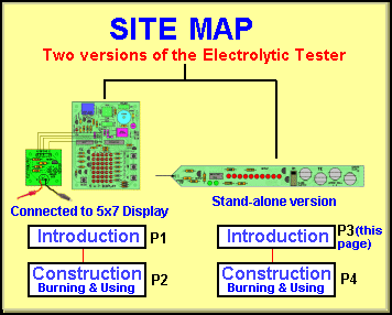
INTRODUCTION
This project is
part of our Microcontroller course. One of the basics of the course is
to show how to adapt a project to suit a PIC12c508A. This chip is not easy to work with as it does not have an EEPROM version and
so you
need to buy a number of EPROM versions and go through the time-consuming
step of erasing them before programming. The EPROM versions are quite
expensive and carry the part number PIC12c508A-JW. We bought 10 and
after a staff member used them for a project, only two seemed
to program correctly, by the time I needed them for this project. Sorting
out the good devices from the bad took quite a while as I didn't expect the chips to
be faulty. Buying these types of chips makes a project very expensive
and for this reason it is very difficult to promote this very handy
microcontroller.
The normal 508A's are One-Time Programmable (OTP) devices and the most hobbyists
are not going to buy EPROM versions or waste a OTP chip, every time a program needs a
modification.
Our approach to this expensive problem is to do all the development work with a PIC16F84 and only use
those features that are common to both chips. This is quite easy to do and
this project demonstrates how easy it is to glide from a PICF84 to
a '508A.
We developed this project in a PIC16F84 and when the program worked
perfectly, it was a simple matter of plugging in the adapter plug/socket
(shown below) and
using a '508A. The first time the circuit was converted, we used a -JW
chip and when that ran correctly, a '508A was burnt.
THE ADAPTER
SOCKET
The 18-Pin to 8-pin adapter plug/socket is for those who are
designing their own projects with a PIC16F84 then wanting to fit a
PIC12c508A into the circuit and see how it works. You must only use RB0 to
RB5 and make sure RB3 is input-only. This is how we designed the
Electrolytic Tester. It is much more convenient to design with a PICF84 than
a '508A.

Note: pins 12&13 are not used.
The only line that is directly coupled is pin 9 to pin 4. All the others cross from one side of an IC socket to the other sire of the other socket. The links are made by inserting tinned copper wire into the socket and bending the wire to touch the correct pin on the 8-pin socket. You will have to cover (sleeve) the wires so they do not touch any of the other wires. You can keep the plugs close together but they cannot touch as only one of the pins is wired directly from bottom to top. A small amount of tape around the two sockets will create a firm connection.
THE BOARD
The PC board for the Electrolytic
Tester (508A version) is shown below. It is a stand-alone project and the
board is long and thin with a probe at one end and an
earth clip on a lead. This makes the Tester very easy to use as you can probe the positive
lead of the electrolytic on the project-under-test and push the
"Test" button to get a readout.

HOW THE CIRCUIT WORKS
With the limited number of input/output lines on a PIC12c508A, many of the
projects you design with this chip will require clever circuit engineering.
This project is an example.
The chip has only 5 output lines (these can also be configured as input) and
an input-only line (GP3).
We need to illuminate 10 LEDs to produce a readout from 0 to 9. If we had 7
lines we could use a 7-segment display but we don't have 7 lines!
By placing the LEDs in a 3x3 matrix we need only 6 lines to access any of
the LEDs. This can be further reduced to 5 lines by gating two lines
(producing an AND gate) through
two transistors. The '508A microcontroller can now be used!
The circuit below is the result of our clever design.

The 6th LED is on the
board but it is not driven. In place of driving the 6th LED, the program
illuminates the 5th & 7th LEDs at the same time.
The circuit looks very simple but the components in the "font
end" provide a very accurate discharge-time.
The components are the 220R and the voltage-reference (made up of the
two green LEDs). A green LED produces a characteristic voltage across it of 1.9v. Two LEDs
produce 3.8v across them and this
voltage remains very constant. This voltage is exactly the same as if a
3v8 zener diode was in circuit. This means it does not matter if the voltage
on the power rail rises or falls - our testing voltage remains constant.
The electrolytic-under-test is charged to 3.8v. This gives it a known
amount of energy and if it is 1u, it will have
"one-unit" of energy. If it is a 100u, it will have 100 units of
energy. If we place a resistor across this electrolytic, it will take one
unit of time to discharge the 1u and 100 units of time to discharge the
100u. The resistor we are talking about is the 220R when the micro line is
taken to 0v. Our second accurate voltage-point is the lower voltage-level. This is
detected by the base of a transistor. The electrolytic is discharged between
3.8v and 0.7v.
Using this information, we can start to produce a program.
Go to: Page 4