Beginners Guide
to Electronics
by Martin T. Pickering
Last updated on November 23, 2008
This book gives simplified explanations of how some electronic components work in a circuit. It also gives practical examples of building 2 simple projects. The physics isn’t complex and it doesn’t attempt to explain the ins and outs of “electrons”, “atoms” and such like. Instead, it will give you an understanding of what the components actually DO so that you can immediately begin to design your own simple circuits. The book may be copied as many times as required within an educational system.
INTRODUCTION
I first became interested in electronics when I was age 10 (as long ago as 1961). In those days, transistors were only just being introduced and most equipment still used thermionic valves or “tubes” as the Americans would call them. Much of my learning was by practical experiment. I blew my Dad up only once by connecting 350 volt capacitors the wrong way round; electrocuted the window cleaner (but not fatally) and gave myself several high voltage shocks during the learning experience. This is not to be recommended so just remember that voltages in excess of 50 volts can be painful, if not downright dangerous. Anyway, I hope you enjoy my book. I guarantee it will be more interesting than any previous electronics course at school or college and you’ll understand how the components work after just a few minutes - not the fifteen years it took me to get a grip on it!
©2008 Martin T. Pickering B. Eng.
LET'S START
What's the Difference between A.C.
and D.C.?
 |
Everyone
knows a battery or cell gives "d.c." or "direct current"
and even though these letters do not mention the word "voltage"
they actually mean "steady voltage." to power your radio or whatever. Less understood is "a.c." which stands for "alternating current"
and this actually means a rising and falling voltage. It's important to understand the difference. You wouldn't connect your 12 volt radio directly to a mains power plug because you know the plug gives 110v or 230 volts. Let's take a quick look at the method of making electricity. In a power station, electricity can be made most easily by using a gas or steam turbine or water impeller to drive a generator consisting of a spinning magnet inside a set of coils. The resultant voltage is always "alternating" by virtue of the magnet's rotation. Fig.1 indicates how the voltage rises positive then goes negative. Now, alternating voltage can be carried around the country via cables far more effectively than direct current because AC can be passed through a transformer and a high voltage can be reduced to a low voltage, suitable for use in homes. The electricity arrives at your house is alternating voltage. Electric light bulbs and toasters can operate perfectly from 230 volts a.c. Other equipment such as televisions have an internal power supply which converts the 230 volts a.c. to a low d.c. voltage for the electronic circuits. How is this done? There are several ways but the simplest is to use a transformer to reduce the voltage to, say 12 volts a.c. (Fig.2) This lower voltage can be fed through a "rectifier" which combines the negative and positive alternating cycles so that only positive cycles emerge. |
 |
|
This "rectified" voltage (Fig.3) is suitable for powering things like filament bulbs and electric trains but it is still no good for electronic circuits. What you need is "regulated d.c." which truly simulates the steady voltage you get from a battery (cell). The first step is to connect a large value capacitor to the output of the rectifier. A capacitor acts as a voltage reservoir and has the effect of smoothing the "ripples". |
|
The output (Fig.4) is still not the same as a battery but it's often good enough for charging batteries in mobile phones, but if you connect it to stereo equipment, you will hear the ripple as an annoying background hum. The final step is to pass this "rippling d.c." through a regulator unit. This effectively reduces the ripple to leave almost pure "regulated d.c," suitable for powering electronics equipment such as stereos. |
 |
A high-quality Regulated Power supply is capable of supplying 1.5 Amps (1,500 milliamps) of current. A rotary switch provides selection of 3, 4.5, 6, 7.5, 9 or 12 volts "regulated d.c." It has a multitude of uses, including speed control for a mini drill, amplifiers, CD players etc. |
How does a Resistor Work?
 |
Imagine water flowing through a pipe. If we make the pipe narrow then this will restrict the flow of water. If we force the water (current) through the narrow gap by increasing the pressure (voltage) then energy will be given off as heat. In addition, there will be a significant difference in pressure (voltage) above and below the restriction. As an example, imagine pumping up a tyre by hand. The narrow pipe of the pump gets hot doesn’t it? In electronics we use a resistor when we need to reduce the voltage across the terminals of a circuit. This reduced voltage will cause a lower current to flow. |
 |
On the left is the symbol used to represent a resistor. You may also see it drawn as a zigzag line. A resistor is defined by several parameters: Resistance in Ohms (R) Heat Dissipation in Watts (W) Manufacturing tolerance (%) |
 |
Resistor Colour
Code The value of a resistor is either printed in normal characters or, more usually, as coloured bands. Here is an example. The first band is red, indicating the number 2. The second band is also red, indicating 2. The third band is yellow, indicating 4 zeros. The fourth band is gold, indicating 5% tolerance. (Silver would indicate 10%, brown = 1%, red = 2%) This resistor is 220,000 Ohms in value, often written as 220k. As the tolerance is 5%, the actual resistance lies between 209000 and 231000 or 209k and 231k due to manufacturing inaccuracies. Take a box of resistors. Work out the value of each then check with a meter to see if you are correct. Note that the last band on the resister indicates the tolerance. |
All the colours for 5% tolerance resistors:
  |
  |
  |
  |
 |
The left diagram shows two resistors connected "in series". The
total resistance from end to
end is equal to the sum (addition) of each resistance. So, if each resistor
has a
value of 2200 (2k2) the total value will be 4k4.
Two resistors can be used to set a specific voltage. For example, if two
resistors are connected as shown (left) and a voltage of 10 volts is applied to
the ends, if both resistors are of equal value, the voltage at the centre will be 5 volts. The voltage is divided between the two resistors.
In addition, a resistance can be obtained by connecting two resistors in series to get a value you do not have. There is a very important equation known as "Ohms Law". I = V/R Current (in mA) = Volts divided
by Resistance (in k ) or |
How do Diodes Work?
 |
A diode allows current to flow
in only ONE direction. If the cathode end (marked with a stripe)
is connected so it is more negative than the anode end, current
will flow. The diagram shows three types of diode: Small signal
diode, Rectifier diode, and Fast recovery diode. A diode has a forward voltage drop. That is to say, when current is flowing, the voltage at the anode is always higher than the voltage at the cathode. |
 |
The
actual Forward Voltage Drop varies according to the type of
diode. For example: Silicon diode = 0.6 to 0.7v (depending on type) Schottky diode = 0.3v Germanium diode = 0.2v In addition, the voltage drop increases slightly as the current increases so, for example, a silicon rectifier diode might have a forward voltage drop of 0.7v when 100mA is flowing but 1.0 volt when 1 Amp is flowing. |
 A Red LED |
An LED is also a diode.
Each colour has a characteristic voltage drop that cannot be altered. The actual voltage-drop depends on the manufacturer Red = 1.7v to 1.9v Green = 2.1v - 2.3v Orange = 2.2v - 2.3v Blue = 3.2v to 3.6v White = 3.2v to 3.6v |
 |
A ZENER diode does not allow current to
flow until the voltage on its cathode reaches a value called the
"Zener Voltage." At this voltage the diode "breaks down" and a LOT of current
will
flow and must be restricted by connecting a resistor in series.
At this point the supply voltage can increase and the voltage
across the zener will remain constant. Values of 2.4 volts to 100 volts or more are common. Zener diodes are used to "clamp" a voltage in order to prevent it rising higher than a certain value. This might be to protect a circuit from damage. Zener diodes are also used to provide a fixed "reference voltage" from a supply that varies. They are widely used in regulated power supply circuits. |
How do Transistors Work?
 |
Here is a picture of a transistor.
It runs on water but is a very good example of how a transistor
operates. There are three openings labelled "B" (Base), "C" (Collector) and "E" (Emitter). We provide a reservoir of water "C" (the "power supply voltage") but it can't move because there's a black plunger in the way which is blocking the outlet to "E". The reservoir of water is called the "supply voltage". If we increase the amount of water sufficiently, it will burst our transistor just the same as if we increase the voltage to a real transistor. We don't want to do this, so we keep that "supply voltage" at a safe level. If we pour water current into reservoir "B" (the base “voltage pressure”) this current flows along the "Base" pipe and pushes the black plunger upwards, allowing quite a lot of water to flow from "C" to "E". Some of the water from "B" also joins it and flows away. If we pour even more water into "B", the black plunger moves up further and a great torrent of water current flows from "C" to "E". This is exactly how a transistor works. |
|
What have we
learned? 1. A tiny amount of current flowing into "B" allows a large amount to flow from "C" to "E" so we have an "amplification effect". We can control a BIG flow of current with a SMALL flow of current. If we continually change the small amount of water flowing into "B" then we cause corresponding changes in the LARGE amount of water flowing from "C" to "E". The device has a "gain" or "amplification" factor. In a real transistor we measure current in thousandths of an Ampere or "milliamps". For example, 1mA flowing into "B" can allow 100mA to flow from "C" to "E". 2. The amount of current that can flow from "C" to "E" is limited by the "pipe diameter". So, no matter how much current we push into "B", there will be a point beyond which we can't get any more current flow from "C" to "E". The only way to solve this problem is to use a larger transistor. A "power transistor". 3. The transistor can be used to switch the current flow on and off. If we put sufficient current into "B," the transistor will allow the maximum amount of current to flow from "C" to "E". The transistor is switched fully "on". If the current into "B" is reduced to the point where it can no longer lift the black plunger, the transistor will be "off". Only a small "leakage" current from "B" will be flowing. To turn it fully off, we must stop all current flowing into "B". Notice that we need a certain amount of “voltage pressure” in reservoir “B” before the plunger will move at all. This voltage is approximately 0.6 volts for a silicon transistor. If B is less than 0.6 volts, no current can flow at all. But it can’t be more than 0.6 volts because the black plunger opens and relieves the pressure. In a real transistor, any restriction to the current flow causes heat to be produced. This happens with air or water in other things: for example, your bicycle pump becomes hot near the valve when you pump air through it. A transistor must be kept cool or it will be damaged. It runs coolest when it is fully OFF and fully ON. When it is fully ON there is very little restriction so, even though a lot of current is flowing, only a small amount of heat is produced. When it is fully OFF then NO heat is produced. If a transistor is half ON then quite a lot of current is flowing through a restricted gap and heat is produced. To help get rid of this heat, the transistor might be clamped to a metal plate which draws the heat away and radiates it to the air. Such a plate is called a "heat sink." It often has fins to increase its surface area and thereby improves the efficiency. Getting Technical The difference between PNP and NPN transistors is that NPN use electrons as carriers of current and PNP use a lack of electrons (known as "holes"). Basically, nothing moves very far at a time. One atom simply robs an electron from an adjacent atom so you get the impression of "flow". In the case of "N" material, there are lots of spare electrons. In the case of "P" there aren't. In fact "P" is gasping for electrons. Bear in mind that the Base is only a few atoms in thickness - almost a membrane - so any electrons allowed into the base "membrane" act as a catalyst to allow other electrons to break through from collector to emitter. Imagine a pool of water near the edge of a table. It rests there with surface tension holding it in place. Now put one tiny drop of water on the table edge and let it touch the pool of water. Suddenly, the pool drains onto the floor as gravity takes over! Your tiny drop provided the catalyst to get it moving. So the base electrons do a similar job for the "pool" of electrons in the emitter - helped by the "gravity suction" of the power supply voltage on the collector. A transistor doesn't "increase" current. It simply allows power supply current to pass from collector to emitter* - the actual amount depends on the (small) current allowed to flow into its base. The more electrons you allow into the base, the more (x100) that flow from collector to emitter. I put "x 100" because that is the typical gain (amplification factor) of a transistor. For example, one electron put into the base could allow 100 to escape from collector to emitter. The best way to understand this is to get your soldering iron and start building! The purist might argue that current flows from emitter to collector - dependent on whether we are discussing electron flow or "hole" flow. I don't want to get involved in the real physics of current flow. You don't need to know this to understand a circuit. This discussion relates to Bipolar transistors. Other types of transistor such as "FETs" (Field Effect Transistors) are in common use and work in a slightly different way in that the voltage applied to the "gate" terminal controls the current flowing from "cathode" terminal to "anode" terminal. In effect, a FET is simply a semi-conducting (one-way) resistor whose value is controlled by the voltage applied to its "gate." | |
Example Transistor Circuits
 |
THE VOLTAGE
REGULATOR One of the most commonly used circuits is the VOLTAGE REGULATOR. The simplest design uses just a resistor and a zener diode. In the first circuit on the left you can see a resistor (R1) and a zener diode (ZD1) connected across a power supply. The resistor is connected to the positive (+ve) of the supply and the zener diode anode is connected to the zero volt (ground). At the junction of these two components the voltage is clamped by the zener diode to its specified voltage - in this case 5.6 volts and this is the output of the circuit. |
 |
VOLTAGE
REGULATOR - 100mA The circuit above is suitable for low current but the resistor becomes too hot if a larger current is needed. To cope with this we can add the NPN transistor (Q1). Now the transistor passes the current required. What is the output voltage? It is easy to calculate.
|
| Let's assume the following:
The circuit which this regulator is driving needs 5.0v at a current of 100mA. A BC337 transistor is suitable since it can handle current up to 800mA. Its gain at 100mA is listed as 100 (minimum) so it's easy to see that it will need at least 1mA into its base to allow 100mA to flow from collector to emitter. For the zener diode let's choose a BZX55C5V6. This will need a minimum of 10mA of current to produce a stable voltage. So Q1 requires 1mA, ZD1 requires 10mA, making a total of 11mA through R1. If the minimum supply voltage is, say, 7.8v then the minimum voltage across R1 is 2.2v. (7.8 - 5.6 = 2.2) Ohms law says the resistance = V/I = 2.2/11 = 0.2k resistance = 200 Suppose the maximum supply voltage might be 9.6v. Then the maximum voltage across R1 will be 9.6 - 5.6 = 4.0v. From Ohms Law, the current through R1 will now be V/R = 4.0/200 = 0.02A = 20mA Watts = Volts x Amps milliWatts = Volts x milliAmps Watts = Volts x Amps so the minimum Wattage of R1 must be 4.0 x 0.02 = 0.08W - not a lot! A standard 0.25 Watt resistor will be more than adequate for R1. Let's check the zener diode rating under the worst conditions: The voltage across ZD1 will still be 5.6v The current in the worst case will be 20mA, assuming none goes through Q1. So the Wattage of ZD1 must be at least 5.6 x 0.02 = 0.112W = 112mW A BZX zener diode will dissipate up to 500mW so the circuit is safe. To provide 5 volts at up to 100mA, the final design will use: R1 = 200 0.25W ZD1 = BZX55C5V6 Q1 = BC337 |
VOLTAGE REGULATOR - 5A |
| The 100mA
circuit can be converted to provide more current. All we
need to do is to add a second transistor (which has a
higher rating to handle the extra current) and change
the zener diode to clamp at 6.2 volts in order to
compensate for the b-e voltage of BOTH transistors. 6.2
- 0.6 - 0.6 = 5.0 volts If the first transistor provides 5.6 volts at 100mA (0.1 Amps) and the gain of the second transistor is 50 then it can provide 5.0 volts at 0.1 x 50 = 5 Amps. Be sure to use a power transistor rated at 5 Amps or more! The final design can use: R1 = 200 0.25W ZD1 = BZX55C6V2 Q1 = BC337 Q2 = 2N3055 (on a suitable heat sink) Note: The combined gain of both transistors is 100 x 50 = 5000. We could not use just one transistor because no ordinary transistor capable of handling 5 Amps can have a gain of 5000. We could, however, use a "Darlington" transistor which has two transistors (connected as above) in one package. |
Abbreviations
Although we use the Greek
symbol Omega W
to represent “Ohms” it is frequently written as “R”.
So, for example, a resistor of 47 Ohms may be written as 47W
or 47R.
A resistor of four point seven Ohms may be 4.7W
or 4.7R but, because the decimal point may disappear during
printing, it is common practice to put the letter in place of
the dot, thus: 4R7
A thousand Ohms is called a “kiloOhm” and abbreviated to “k”.
So, for example, 6800 Ohms may be written as 6.8k or 6k8
A million Ohms is a “MegaOhm” and abbreviated to “M”.
So, for example 1,000,000 Ohms may be written as 1M
3,300,000 Ohms may be written 3.3M but the preferred way
is: 3M3
How does a Capacitor Work?
|
|
A capacitor consists of
two separated plates and it is obvious that electricity
cannot pass from one side to the other. And it doesn't.
No electricity flows through a capacitor. But something does happen and it APPEARS that electricity flows through a capacitor. What happens is this: When the capacitor is connected to a DC voltage, electrons flow into the top plate to fill the capacitor. When it is full, the electrons stop flowing. To the casual observer, this looks like the same as current flowing into the capacitor. This only takes a very short period of time and after this, nothing flows into or out of the capacitor. But if the DC voltage contains ripple, this voltage will appear as a changing voltage and charge the top plate. When the ripple reduces, the extra charge on the top plate will be passed back to the top rail. In effect, the capacitor will be charging and discharging to absorb and return the charge and this will reduce the ripple. Spikes are also suppressed as they are simply very high voltages of very short duration. |
|
|
The next
effect produced by a capacitor is called "influence."
You have possibly seen people walking along a wall and
others on the ground teasing them to fall off by
pretending to push. Eventually the person falls. The same with a capacitor. When a voltage on the left side of the capacitor rises, the left-hand plate rises and pulls the right hand plate with it, because both plates at the same zero potential. As the left plate rises, it also collects some of the charge from the rising voltage and it ends up with a slightly higher voltage than the right plate. Let us assume the left plate rises to 20v and the right plate rises to 10v. When the voltage falls, the right plate pushes the left plate down and in the process it loses most of the original charge (potential) and the right plate decreases to zero. The voltage on the right-plate can be used to power a circuit and it would appear that the current has passed through the capacitor. Where does the current come from? It actually comes up from the 0v (ground) lead. This is something that has never been covered before in any text book. Now we come to the final statement: A CAPACITOR BLOCKS DC - BUT PASSES AC |
What does a capacitor look like?
|
|
There are hundreds
of different shapes and sizes of capacitor and you cannot tell
any of the characteristics by looking at the size or shape. You
must look at the values printed on the side of the component and
refer to the manufacturers specifications. Sometimes the shape and colour of the capacitor can take you to a specification sheet for more information. The photos on the left show some of the capacitors available on the market. We could not possibly outline the range of values, the working voltage and the different types of dielectric in this short discussion. The only way for you to gain experience is to desolder some capacitors from the printed circuit boards of salvaged equipment and sort them into different groups. Most of the capacitors will be perfect except for very old electrolytics - as they may have dried out and lost their capacitance. Some of the mall capacitors have coloured shots to identify their capacitance and tolerance. You will need to refer to a chart to determine their value. In most cases there is a reason why a particular type of capacitor has been chosen. It may be due to cheapness, high stability, low impedance, size, shape, high capacitance, low capacitance, high frequency, high voltage, durability, high temperature, temperature stability, variable capacitance (air trimmer) or a number of other factors. |
How do Inductors Work?
Whereas a resistor limits the flow of current, an inductor opposes a
change of flow of current.
So, it allows a steady current to flow freely, but it will not let the
current change rapidly.
It causes a delay to occur in the change and this creates a delay-factor
that can be used in electronics.
An inductor also produces a voltage in the opposite direction when the
voltage is suddenly removed.
This voltage can be considerably higher than the voltage energising the
inductor.
Actually, the operation of an inductor is very complex and would take
many pages to discuss. We will just look at some types:
|
A
small inductor might look very much like a resistor. It will
measure almost short-circuit because it is simply a few turns of
wire. Larger inductors can be seen to be coils of copper wire insulated with varnish Inductors with even more turns are often called "chokes". Some inductors have an opaque insulating sleeve. This sleeve is made from polyolefin which shrinks when heated. This is a high frequency coil from a radio A tiny coil with a metal screening can and an adjustable screw core A small coil with a metal screening can and an adjustable screw core A small coil without a screening can This one looks very much like a transformer but is clearly a choke since it has only two connections. A transformer needs at least three. A screw core made of compressed powdered iron called "ferrite" |
The Relay
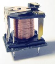 |
A relay is a coil of wire wound
around a soft iron core. Current flowing through the coil turns
the iron into a magnet which attracts a hinged iron lever which,
in turn, closes or opens a set of contacts. The photo clearly shows the lever, coil and contacts. |
LED TORCH
 |
The
circuit shows a LED torch running a LED from just 1.5 volts.
An Ultra-bright white LED usually needs at least 3.6 volts across it before it
will light. This simple circuit uses a single transistor and a
transformer comprising just 60 turns and 40 turns of fine wire
on a tiny ferrite slug to form an oscillator. The circuit will
operate off an almost dead battery (just 0.75 volts) and
produces around 20 volts with the LED disconnected. Up to four
LEDs may be connected in series but the brightness decreases as
the number of LEDs is increased. The circuit demonstrates the characteristics of an inductor mentioned above and the 10n capacitor shows how stabilizing the voltage at the connection of the transformer and 2k7, improves the output of the circuit by 300%. |
Bread Board and building a LED Flasher
  |
Breadboard In The
Early Days Circuits were originally constructed by wrapping wire around brass nails hammered into wooden boards such as those used for kneading dough to make bread. Hence the term “breadboarding” to indicate a prototype layout for an electronic circuit. The modern equivalent of the “breadboard” takes several forms. The most common employs springs fixed vertically to a board. You can push the component wires between the spring coils which will grip the wires and make good electrical contact. This is OK for larger components but not so convenient for I.C.s. So a further development is called by various names like “S-Dec, “µDec” and “BredBord” which consists of a molded plastic block containing strips of springy metal – usually phosphor-bronze or berillium-copper alloy. The top surface of the "deck" is perforated with rows of holes to allow component leads to be positioned easily. (I’ve painted the wires red on the breadboard so they can be seen). The circuit is powered by two 1.5 volt AA cells in a battery holder. Compare the physical layout with the circuit diagram. Notice the I.C. is pushed into eight holes, straddling the central channel. Each of the eight holes is one of a group of 5 which are all connected together horizontally under the plastic. There are two columns, each with 29 rows of 5 interconnected holes. A further four columns, at each side, are connected together internally in vertical sets of 25 holes. (These vertically connected holes were not used in our layout). This type of “breadboard” layout requires no soldering and circuits can be assembled in a few minutes and the components are fully re-usable. |
Building the LED Flasher
|
|
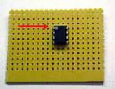
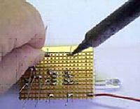
Once the
circuit is proven you can build it. This project is easy to
build on perforated stripboard. We’ll call it by a well known
manufacturer’s trademark “Veroboard®”.
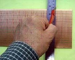
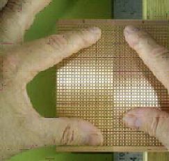
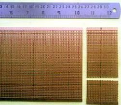
If you start with a large piece of Veroboard, it
needs to be cut to size. Use a sharp blade to score across the board, following a line of holes. Be sure to make an extra deep notch at each edge. Now rest the board over the edge of a table or bench, with a steel ruler or similar sharp edge immediately below the score mark. Apply downward pressure and the end piece should snap off cleanly. Repeat this process to make a smaller piece for this project. Fit the I.C. in a roughly central position and bend its pins to retain it. Pin 1 is indicated by the arrow. Pin 1 normally has a dot or notch just to the right of it. The other pins are numbered clockwise from 1. Look at the circuit diagram and decide where the parts can fit. The LED connects between pins 7 and 8 so that’s easy to do. Wire links are used to connect pins to other tracks. At this stage you should choose where the positive and zero voltage tracks can be. I’ve marked my choice with red and blue lines, respectively. Needle-nose pliers or tweezers are handy for bending and fitting the wires. |
|
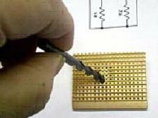
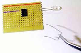
Once you are happy the I.C. is in a convenient
position, you can cut the copper tracks between its
two rows of pins, otherwise they will be connected
together. This operation is carried out simply by
using a twist drill of 3.5 - 4.0 millimetres in
diameter. Make sure each track is cut completely.
If you are unsure of the I.C. position, leave this
operation till later, but do it before you solder the
I.C. pins.
Carry on fitting the components. The actual physical positions of the parts are unimportant. Just make sure that they will be connected to each other and to the I.C. in accordance with the circuit diagram. The physical layout of parts on the board doesn’t have to look exactly like the circuit diagram, although it may help you if it is reasonably close. For a more complex project, you may find it easier to sketch a provisional component layout on squared paper. Bend the component wires underneath the board as you fit each part. This will prevent them from falling out as you fit subsequent parts to the board. At this stage it is easy to pull out parts and reposition them if you don’t like the initial result. When you are happy that you have positioned the components and link wires correctly, solder the wires to the copper tracks. First, be sure to apply fresh solder to the iron tip then wipe off excess on a damp sponge. (The sponge must be a cellulose type as sold for the purpose. Household “sponges” are made of plastic and will melt!) Be sure to press the hot tip against the wire and track, rotating it back and forth in your fingers as you apply the solder to the joint. The rotating motion helps to scrape off oxidised copper to make a good electrical connection. Be sure to apply the solder to the copper track after the tip of the iron has been pressed onto the joint. Applying solder to the iron tip at this stage will result in the solder running up the tip away from the joint! Note that this project can be made on a smaller piece of board. I’ve spread it out to make the layout clearer for you. |
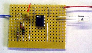 |
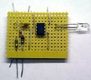
Here is a photograph of the finished item. Compare it with the circuit diagram. Remember the links and components are connected by the copper tracks beneath. The capacitor is polarised and its positive wire is marked with a “+” symbol (red arrow on the board above). The LED is polarised. The cathode lead is identified by a flat spot on the side of the LED. The diode is also polarised and its “cathode” end is marked by a black band. Resistors are not polarised and can go either way round. Notice that the 4700 Ohm (4k7) resistor is marked yellow-violet-red and has a gold band to indicate that it is 5 percent tolerance. The 1,000,000 Ohm (1M) resistor is marked brown-black-green. I’ve used red for positive (3v) and blue for negative (zero volt) battery connections. |
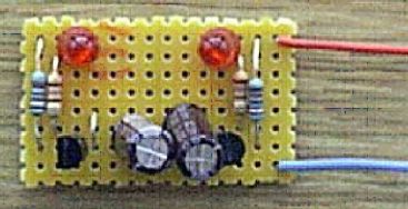
Astable Multivibrator using two transistors
 |
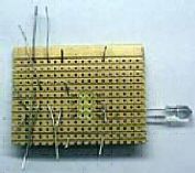
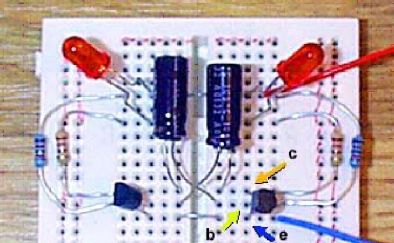
Another
LED flasher You can build lots of interesting and useful circuits without using I.C.s. After all, an I.C. is simply a handy container for a number of miniature components! Here is an extremely common circuit with a multitude of uses - eg. a slow alternating flash for a model railway crossing or a fast rate of flash for a flickering flame. First we can fit the components into a “breadboard” to make sure that the circuit works. The transistors, Q1 and Q2, can be any general purpose NPN silicon bipolar type such as BC547B (as used here). Transistors have three leads we call the “collector”, the “base” and the “emitter”. I’ve marked these with arrows. Resistors R1 and R4 protect the LEDs from excessive current. The actual value is dependent on the characteristics of the LEDs but 270 Ohms should be fine for supply (voltages of between 3 volts and 12 volts are suitable for this circuit). R3 and R4 determine the speed at which the LEDs flash alternately (the frequency of oscillation). Capacitors C1 and C2 also have a big influence on the frequency. For a slow flash of about one Hertz (one flash per second) you can use 100µ electrolytics. For a rapid flash use 4µ7 capacitors. For other speeds try different values. |
This book was written by:
by Martin T. Pickering
|
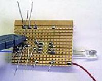
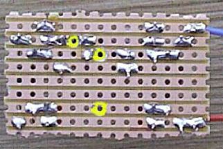
(It’s OK to experiment. That’s what design is all about!) Notice that the negative end of each capacitor is connected to a transistor “collector”. Now let’s put the final circuit onto Veroboard ... Here are the components soldered onto Veroboard, The layout follows the circuit diagram fairly closely but the crossed-over capacitors are dealt with by adding a wire link. Three tracks have to be cut (highlighted in yellow). I have pushed the LEDs down onto the board but you might prefer to leave them “on stalks”. This leaves them prone to vibration-fracture so it’s a good idea to squirt some hot-melt adhesive around the wires to secure them to the board. If you leave the LED wires long, it’s easier to fit the unit into, say, a robot with “flashing eyes”. The photo below shows the circuit on a Robot Man PC board designed by Talking Electronics. See Talking Electronics website: http://www.talkingelectronics.com |