|
|
|
P1
P2
P3 |
This project is
a mini "GAMES CONSOLE."
It comes with two games and the idea is to create more of your own games by
looking at the programs we have provided and work from there.
The games have been
Hand-coding in assembly uses the 35 instructions that come with the PIC micro and these instructions are all you need to get it to perform all its operations (capabilities).
We could write the program in "C" or PICbasic" or some other form of programming language but this would put you at "arms length" with PIC chips as the instructions would not be PIC instructions.
Writing in assembly is the starting-point to learning to create a program.
It will only take a few days to learn the 36 instructions as they are not difficult to remember.
They are called mnemonics and this means they consist of letters of a word or the first letter of a number of words.
Examples are: btf (bit test file) decfsz (decrement file and skip the next instruction if not zero).
We have also made programming easy by providing a library of routines so you can "cut and paste."
If you follow our suggestion of adding a few instructions at a time or one sub-routine at a time, you cannot go wrong. This is the way we create programs and it saves a lot of frustration. If something does not work, the last few lines are at fault.
There are a number of debugging tools and single-stepping routines, but they all take skill to operate and they can finish up more frustrating than following our method.
THE CIRCUIT
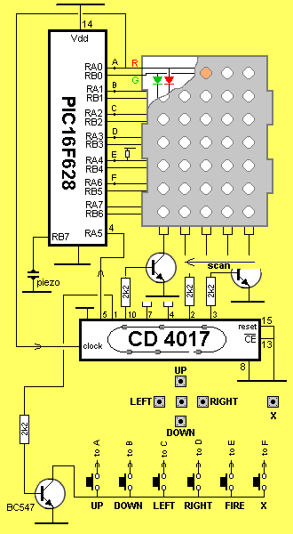
The basic circuit:

DUAL LED 5X7 DISPLAY
The PIC micro is constantly executing 1 million
instructions per second and you can put it in a loop and do nothing or
create lots of interesting effects on a 5x7 Display.
There are two ways to get "things'" to appear on the display
SCREEN DUMP
The first method is to "dump" or
"illuminate" one or more pixels (LEDs) on the screen by accessing the
associated row and column connections.
It is not possible to illuminate some combinations of LEDs as other LEDs
will also illuminate at the same time.
So, this method is limited to a few combinations.
The transistors driving the LEDs have current limiting resistors (not
fully shown in the diagram above) and
these are designed to deliver a high current for the scan routine. If we
turn on a single LED or just a few LEDs, they will appear extra bright -
via the DUMP method.
This can be avoided by pulsing the LEDs, and will be discussed later.
SCANNING
The solution to illuminating ANY combination of LEDs (there are 70 LEDs)
is to turn on one column at a time and if this is done very fast, we can
illuminate the whole screen. This is called a "Persistence Of Vision"
trick. It's the same as the frames of a movie film producing movement on a
cinema screen. The eye holds or retains an image for a short period of
time after the image has extinguished and this allows us to illuminate
the display.
A complete column of LED are illuminated at the same time and this can
be up to 14 LEDs. As can be seen from the diagram above, if the red line is taken HIGH and
the 4017 is reset, then clocked so that the first output is HIGH, the
transistor will connect the cathode of the red and green LEDs to the 0v
rail and the red LED will illuminate.
If both red and green LEDs are activated, the result will be yellow
(orange).
At the same time, any or all the red and green LEDs in the first column can
be activated.
The required LEDs are illuminated for a very short period of time and
then turned off.
The 4017 is clocked so that the next output connects the second column
to the 0v rail and the required LEDs are activated via the 14 lines from
the PIC chip.
This process is repeated very quickly so that all the LEDs can be
activated.
If we produce a sub-routine to do this, we can illuminate any
combination of LEDs.
Even if we are illuminating one LED, the sub-routine can be called
and it will produce a blank (black) screen in which only one LED is illuminated.
This sub-routine is called the SCAN routine. In our case the scan routine
is called a RASTER routine.
A raster is the white screen produced on a TV when no channel is
selected. It may be speckled due to "snow" or noise being picked up.
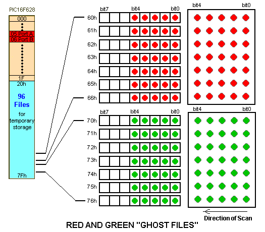
In our case the RASTER is produced by a sub-routine taking data
from files 60h to 66h to produce the red pixels and files 70h to 76h for
the green pixels.
To make it easy to illuminate pixels on the screen, we have only used
the 5 lower bits of each file. If the 7 files for each colour are
laid out as shown in the diagram below, the bits correspond directly to
the pixels on the display. By making a bit = 1, the corresponding LED
is illuminated.
Each output line of the PIC chip is capable of delivering 25mA. To
illuminate the display in multiplex or "scan" mode, we need to deliver
slightly more than 25mA to each LED as we are only illuminating it for
20% of the time.
If we deliver 40mA for 20% duration, this works out as 5mA on a constant
basis. But LEDs do not work on a linear scale and neither does your eye.
A LED delivered 40mA for 20% duration will appear brighter than one
being delivered 5mA on a constant basis and this is why multiplexing is
so successful.
But a PIC chip cannot deliver 40mA so we need buffer transistors. The
same applies to the CD 4017. It can only deliver about 10mA per output
and it also needs a set of buffer transistors.
RASTER ROUTINE
The Raster sub-routine does only one thing. It takes the data from the
14 files and puts it on the screen. This is done very quickly so that
you cannot see any flickering. In fact only one column is displayed at a
time but by scanning very quickly (faster than 100 times per second) it
appears that all LEDs are illuminated at the same time.
It's the same with the raster on a TV set. The screen is illuminated by
a single dot moving across the screen very quickly and producing more
than 625 lines to fill the screen.
The direction of scan has been chosen so that bit 0 can be sent to the
display and then the files are shifted right so bit1 is in bit0
location and can be sent to the display.
After 8 shifts, the files are back to their original value for the next
scan of the display.

ANIMATION
At the beginning of each scan, bits in each file are "1" to represent an
illuminated LED. Before the scan is started, we can manipulate the bits
by moving or shifting them within the file or to another file in the set
of Ghost Files and when
the scan sub-routine is performed, the pixels will appear to move.
SYNC
There is a requirement called
SYNCHRONISATION. The output of the CD 4017 must be known by the micro so
that the correct LEDs will be illuminated on the display.
The CD4017 is clocked by the PIC chip but it must know which output is
active at the beginning of the scan cycle.
We do not have sufficient lines from the micro for a reset line so an
ingenious alternative is to connect one of the outputs of the CD 4017 to
the input line of the PIC and clock the CD 4017 until this output is
detected.
The micro now knows the state of the CD 4017 and every 10 clock pulses
will bring it to the same state.
TWO PIC LINES
You will notice the PIC16F628 has two
lines that are not fully input/output. These are RA4 and RA5. RA4 only
pulls down and must be pulled high via a resistor. RA5 is input only.
6-BUTTONS
The board has 6 buttons. Four control the direction of the "cursor" and
the centre button has been called FIRE. The extra button can be
programmed for any other application.
DETECTING BUTTONS
The circuit diagram above does
not show all the componentry and does not show how the buttons are
detected.
The buttons are "polled" (looked-at) during the scan routine where the
in-out lines of the PIC are converted to input and if one of the buttons
is pushed, it will be detected as a LOW.
The software can detect two buttons at the same time and a sub-routine
can be written to detect the press of a button before the project is
turned on. It actually detects the press of a button at the absolute
instant of turn-on. You can also detect repeat pressing or a code made
up of a sequence.
THE POSSIBILITIES ARE
ENDLESS
The possibilities with this
simple display are endless. The display will produce a number of colours
including red, green and orange and you can illuminate any combination
of LEDs via the scanning routine.
This will give you the capability of producing simple attack games,
strategy games or something new.
When we thought everything had been invented, along came the Rubik's cube
and Tetris.
One area that has not been addressed is the birthday present from an
Auntie. The auntie will generally want to post the present and it needs
to be small and thin for easy posting.
This game is ideal. There is also a demand for games for children in
hospital and lots of other occasions.
The secret is to produce something that grabs the players attention and
nothing is better than "playing against the computer."
Games like "Reversi," "Simon," "Tic Tac Toe," "21 Pegs," are all
possible.
Talking Electronics has been producing simple games for over 30 years
and one of our readers Cameron Shepherd, started by producing a "space
Invaders" game for our Z-80 computer. He then went on to produce games
for Nintendo and now has his own software company based in the UK.
There is still a market for games that can be easily posted.
Nothing fills this "niche" at the moment.
Be the first.
STRATEGY GAMES
Programming a game of strategy requires the highest level of thinking as
you need to create sub-routines that take all possibilities into
account. It's only by covering all possibilities, that a computer
appears to have "intelligence."
Writing a program for a game is like writing a book. You need to get all
your facts together and work out what you want to do.
Obviously the limitation of the game is decided by the 5x7 set of
"pixels" but since these can be 1-of-3 colours or flashing, the
end-result can be quite impressive.
Before you do anything, read through the programs we have
developed and see how the sub-routines perform particular functions.
You will be using many of the pre-written sub-routines and it's just a
matter of starting with the scan sub-routine and loading the Ghost Files
with data for the start of a game.
To create movement or "animation" you will be calling the scan
sub-routine a number of times before the display is updated.
This will give you the speed of the fastest object. Slow objects will
call the scan sub-routine less frequently.
MINEFIELD-1
Minefield-1 is a simple memory
game.
The display is set up with 4 mines and these are turned off after 3
seconds. Your object is to traverse the whole display without touching
any of the mines. You can cheat by pressing the "Fire" button and seeing
where you have travelled and where the mines are located.
You can go over any location more than once to fulfill your task.
MINEFIELD-2
This is the reverse of Minefield-1. You are required to throw a hand-grenade at each mine and blow it up. Guide the hand-grenade by pressing
the 4 direction buttons and press "fire" when the grenade is in
position.
