|
|

Chapter 4
|

If you have
programmed a microcontroller before or are new to programming, the
latest "trick in the book" is ISP.
This is: "IN CIRCUIT PROGRAMMING."
This article will help you connect PICkit-2 programmer to a fully
developed project that has 5 pins. These pins connect to the PIC chip
and also accept a 6-pin to 5-pin connector (available from Talking
Electronics).
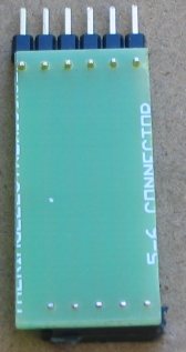
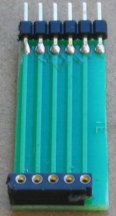
The following photo shows the top and bottom of the
connector designed by Talking
Electronics
to interface between the programmer
(PICkit2) and the PC
board:
 |
 |
Imagine developing a surface-mount project and being able to update the
program while the chip is soldered to the board.
Obviously this is essential for a surface mount design as it is totally
impractical to desolder the chip to change the program.
In this project we show how to design a PC board to contain the 5-pin
ICSP (In-Circuit Serial Programming port).
We have also written a number of projects using a surface-mount microcontroller.
These project are all available as a kit with a pre-programmed micro,
but if you want to modify the program, you will need a programmer and an
interface cable.
Also, if you want to design your own surface-mount project, this article
will get you started.
This article help you with the simplest 8-pin surface-mount PIC
microcontroller.
It is a PIC12F629 8-pin surface mount device with the code number
PIC12F629-I/SN 8-pin SOIC
(Small Outline Plastic Packages)
150mil.
The package is identified by: SOIC-8.
The surface mount version of a PIC12F629 is identified by "I/SN."
The 8-pin dial in line version is: PIC12F629I/P
Pin 1 identification of an
8-pin surface mount chip
PIC12F629I/SN
This chip has a small memory, but don't let that put you off. We will be
producing projects equal to up to 10 of the old-style chips and some of our
projects will even appear to be "intelligent."
When writing a program understood by the microcontroller, the term is called
"Machine Code." But since a chip only understands 0's and 1's, it is
very difficult for humans to remember an instruction with a number such
as 10110101101100. To make it easier, manufacturers have created instructions
that look like the words of the instruction. These words are called
mnemonics and the chip we are using has only 33 instructions. A typical
instruction is: Increment a file and skip the next instruction if the
file is zero.
The mnemonic is: INCFSZ - each letter in the instruction corresponds to
a word in the instruction. All the other instructions are the same, and
we can add more information to the previous instruction by identifying the
file-number and if the result of the increment is placed in the same file or
sent to another file called the "working file."
All this can be placed on one line of your program thus: INCFSZ f,1.
The
chip has 1,024 locations for instructions.
Some instructions carry out a simple task such as setting or clearing a
bit: BSF file,bit BCF file,bit while others can swap the contents of the working register
(W) with a file.
SWAPF file,0 SWAPF file,1
where "0" represents the working register (W) and "1" represents the
same file named in the instruction.
See the PIC12F629
Instruction
Set.
Although the chip looks small and has only 8 pins, two are for
connecting to the power and 6 lines are in/out. The chip can control 5
devices and one line is input only (pin 4). The 5 output lines can be changed to
input at any time during the running of the program and this gives you
great flexibility.
The functions for
each pin:
Note: Pin 4 is INPUT ONLY
These chips are not a "computer on wheels" but they will get
you started into the world of programming and thinking of ideas that
could lead you down the path of invention.
To give you three examples, an inventor in our club designed a letter
bomb detector from a gold detector and went on to sell nearly 1,000
units and realise nearly $3.5M in sales. 7 people have been saved from
unknown explosive devices and he sells his invention throughout the word. If he had put the
requirements into a chip as simple as the one we are promoting, his
circuit would be 75% smaller.
Another designer built a telephone number storage device for 20 numbers.
He used 16 chips. Our chip would carry out the task without any other
components.
Another designer produced a medical timing device for patients and sold
it to a drug company. His chip was
added to a speech chip and everything was produced as a "COB." (Chip On
Board). He had 200,000 made. It had 20 seconds of speech, controlled by
turning the cap of the bottle. It explained when to take a tablet.
These are just some of the possibilities.
The microcontroller can do things like turning on an output (making it
go HIGH) and keeping it HIGH for any length of time. By making an output
go high/low/high/low, the result is a tone.
An output has sufficient ability to drive a LED (25mA) and this gives us
the ability to drive 5 LEDs at the same time.
The other line can be used as an input.
A LED will turn on and off very fast and when they are moved through the
air and activated correctly, the result is writing. That's why we call
the project SKYWRITER.
START HERE
The first thing you must remember is this: 3 pins are needed for IN CIRCUIT PROGRAMMING. These are pins 4, 6 and 7. Pin 4 is an input-only pin. Pins 6 and 7 are GP1 and GP0. If you need to connect devices to pins 4, 6 and 7, the programmer needs to drive the pins HIGH and LOW during programming..
It is capable of delivering more than 25mA (in other words it has a low output impedance of about 40 ohms) but do not connect a capacitor or electrolytic to these pins as the electro will prevent programming. Pin 4 needs to go HIGH (about 14v) during programming, so any device sending a signal to the pin needs to accept 14v, see below:
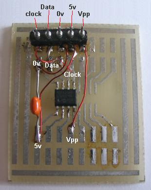
The following diagram shows a SURFACE MOUNT PC Board with a PIC12F629 chip and IN-CIRCUIT PROGRAMMING socket made from 5 tinned copper wires.
The photo identifies each of the pins for the surface-mount chip:
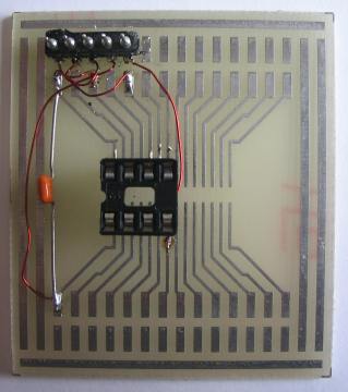
The photo below shows fine
enamelled wire (0.2mm) connecting the programming pins to an 8-pin IC
socket:
The names of each of the pins for the 8-pin IC socket:
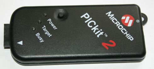
1. What is a PICkit 2? The PICkit 2 is a USB in-circuit prototype programmer manufactured
(and sold) by
Microchip. The PICkit 2 contains an 18F2550 chip. This chip can update its code
(write to its own FLASH memory). The PICkit 2 contains a bootloader that
makes this possible. You can use this feature to update the firmware of
your PICkit 2. With the latest version of MPLAB (7.41) it should be possible to use
the PICkit 2 as an ICD (in-circuit debugger, like ICD1 or ICD2), but
only with the PIC16F917. So far I have not been successful with this.
The PICkit 2 is an in-circuit programmer, which means that it does
not have a ZIF or similar socket to plug the target chip (the chip to be
programmed) in. Instead it has a connector for a 6-pin, which you must
connect to the target chip. With some care this enables you to program
the target chip without removing it from its circuit. To be really sure that a PIC is correctly and long-term reliably
programmed it must be verified (by reading the code back and comparing
it to the original) at the low and high extremes of the power supply
voltage that it will be used with. Microchip calls a programmer that can
do this a 'production' programmer. A programmer that does not have this
capability is called a 'prototype' programmer, indicating that it should
not be used for development only, not for production work. The PICkit2
hardware has a limited ability for varying the supply voltage for the
target chip (it can only regulate down from the voltage supplied by the
USB connection, and its only reference is that voltage), and the current
PICkit2 software uses this ability only to reduce the supply voltage to
3.3V for chips that cannot use a higher voltage. Hence the PICkit2 is
called a 'prototype' programmer. Generally speaking a bootloader is a (small) program, which sole
purpose is to load another program (the application) into memory (and
probably to start that application). In the context of FLASH
microcontrollers a bootloader is a program that can write an application
program to the FLASH memory of the microcontroller (it can of course
write only to the part of the FLASH that is not occupied by the
bootloader itself). The PICkit 2 contains a bootloader that will takes
control when the PICkit 2 is powered. When the bootloader does not find
an application program already in FLASH, or it finds the PICkit 2 button
pressed, it will remain in control. Otherwise it will pass control to
the application program (the PICkit 2 firmware itself). When the bootloader is in control it will blink the Busy LED. 5.
How can I download/update the PICkit2 firmware'? The PICkit 2 XP program supplied by Microchip has a menu entry
'Download PICkit 2 OS firmware' under 'tools'. This will instruct the
PICkit 2 application to pass control to the firmware and let you pick a
.hex file to be downloaded. If your PICkit 2 contains the bootloader but no application the
bootloader will remain in control (the Busy LED will blink). When you
start the PICkit PC program it will take some time during which nothing
seems to happen (don't panic). Then a window appears that allows you to
choose the application .hex file to download. This also takes some time.
Then the normal PICkit 2 application window will appear, but it shows a
nonsense message about a strange firmware version. You can ignore that
message.
6. The software in my PICkit 2 seems to be corrupt, what can I do?
If an application is present in the PICkit 2 but it is corrupted (or
it is not the PICkit 2 firmware) you can not use the normal software
update method. Instead you must plug the PICkit 2 in (USB cable) while
pressing the button. This forces the bootloader to invalidate the
application and take control. Now you can proceed as stated in the
previous answer. 7. What is the
purpose of that button? The PICkit2 has a small black button right above the power LED. When
it is pressed while the USB connection is made the bootloader will claim
control instead of activating the PICkit2 firmware. This can be used to
update a damaged firmware. The PICkit2 hardware has two 24LC512 EEPROMs. With the current
firmware these EEPROM are not used. With appropriate firmware (which to
my knowledge does not yet exist) the PICkit2 could be used as a
stand-alone programmer: use a PC to load the software update into the
EEPROMs, drive to the device you want to update, plug the PICkit2 in,
press the button, and the new software is programmed into the device.
The device must provide power to the PICkit2, and the target PIC must be
one that can be programmed with a Vdd-before-Vpp sequence. 8. Which USB driver do I
need? You don't need a special USB driver, the PICkit 2 uses the HID (Human
Interface Device) driver that is part of Windows XP. 9.
I get 'USB device not recognised', what should I do? This problem is often reported by PICkit 2 users. I don't have a
definitive solution, but some thing seem to help: disconnect the PICkit 2 from the target circuit before you
connect the USB cable
plug the USB connector in slowly (this increases the time
between the power contacts connecting and the data contacts
connecting)
when you get the error, disconnect, wait a few seconds, and
reconnect.
contrary to the above, some people have reported that you must
wait a long time (>30 seconds?) before you attempt to reconnect. I
suspect that this is a cure for a different problem.
if the PICkit 2 is connected to a HUB, disconnect the HUB from
the PC and reconnect (I still saw the 'USB device not recognised'
error but the device did work!)
(a bit experimental) during experiments with a PICkit 2 clone I
am designing I noticed that the 'USB device not recognised' was
produced by the PICkit 2 application, never by the bootloader, and
also never immediately after the application was downloaded and
started by the bootloader. The USB part of the application and
bootloader work a bit different, so I reasoned that maybe the
bootloader does a better job on the USB initialisation. But the
original bootloader does not initialise the USB, except when no
application is present, or the button is pressed. So I modified the
bootloader to *always* initialise the USB, wait a second, shut down
the USB, and then start the application (if present). You can hear
this: when you plug it in you hear a USB attach, USB detach, and a
final USB attach. So far I never got the 'USB device not recognised'
with this modified bootloader. To use this bootloader you will have
to re-program your PICkit 2. When you open it you will notice a
strip of 6 pads at the edge of the PCB. These pads can be used to
(re) program the 18F2550 in the PICkit 2 with .... a PICkit
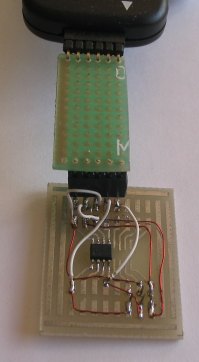
IN-CIRCUIT PROGRAMMING
CONNECTIONS
The photo below shows fine
enamelled wire (0.2mm)
connecting the programming pins to the
surface-mount chip
and MicroChip PICkit-2 programmer: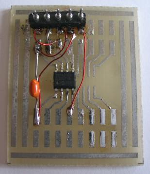
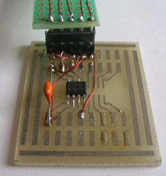
The connector and surface-mount chip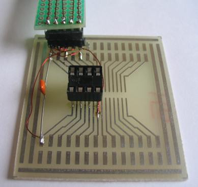
The connector and 8-pin IC socket
2. What is 'in-circuit'?
3. What is 'prototype'?
4. What is a 'bootloader'?
5. How can I
download/update the PICkit2 firmware'?
6. The software in my PICkit 2 seems to be corrupt, what can I do?
7. What is the purpose of
that button?
8. Which USB driver do I need?
9. I get
'USB device not recognised', what should I do?
If you want the
PICkit-2 serial
programmer to be connected constantly to a chip during the development
of a program, it has a number of limitations when programming a chip
that is connected to low-impedance devices.
When a chip is being programmed "in circuit," some of the devices being
driven by the chip are activated during the programming operation.
Even though each output is only capable of delivering 25mA, the combined
current from 4 outputs on the Random Number project was sufficient to
create a problem. The current taken by the circuit was in excess of the
current-capability of the components in the PICkit-2 and the
output voltage dropped excessively - preventing the chip being
programmed.
The solution was to drive the circuit from the supply powering the
circuit and have a switching transistor to do this when the programmer
was in program-mode. This removed the excess current from the
programmer.
WHERE TO, FROM HERE?
Buy: ICSP-1t (In Circuit
Programming board for through-hole chip plus IC socket and plug
and wire and fine solder) Approx $7.00
or ICSP-1s (In Circuit Programming board
for
surface-mount chip and plug, wire and fine solder) Approx $7.00
To place an order, click:
ICSP PC boards
Buy: PICkit-2 serial programmer and interface lead.
Approx $40.00
Place the chip on the board and all the components from the kit. You
will need a 5v supply made from 4 AA or AAA cells. Connect the interface
lead to the board and PICKit-2. Connect the PICkit-2 to the USB port on
your computer and insert the MPLAB IDE CD that comes with
the programmer.
Load MPLAB onto your computer.
Now go to: Start
HERE with PIC12F629 to learn how to write a simple program for the
chip.
You will need Notepad2 (.zip) or
Notepad-2 (.exe) to load
PIC12F629 template. You can then modify the
template to create your own program.
5/5/10