|
PIC MINI DICE |
|
by:
Rickard Gunée |
Introduction
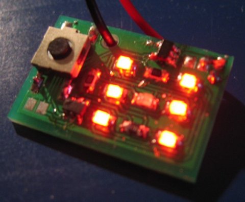
This project describes a PIC10F200-based electronic dice. The reason I made this was that I had a small corner left over when ordering a panel with a couple of other PCBs and thought I would rather use the corner for something interesting than leave it unused, so I made a dice project. The PCB is quite small, so it is hard to etch it yourself.
Even though this is a very simple project, it requires some surface mount soldering skills, proper tools, and a steady hand as it is built with surface mount components only. But it might be a good start if you have experience with through-hole soldering and want to try surface mount.
The complete project
Hardware
The standard solution for a power supply is to use a 7805 but I could not
find any 7805 in a sot-23 or smaller outline so I used an LP2985 that is
available in a 5-pin sot-23 with 5v/150mA output. I use a 100nF cap
on both input and output side of the regulator to get rid of noise etc. I'm
using a standard 9v battery to supply the circuit. In the PCB-layout there
is also a hole for the cable to remove mechanical tension from the soldering
point.
The PIC controlling the dice is a PIC10F20X, but it is also possible to use a
PIC10F22X (that is what is sold in my web shop as it is almost the same price
so I use the 10F222 to get fewer chips in stock as other projects use the
10F222), both are microcontrollers with very limited RAM and ROM, 16b/256w of
RAM/ROM but there are versions with up to 24b/512w. The 10F22X series also has
an ADC but that is not needed in this project. Two of the six pins are used for power
supply, there is one reset (or input only) pin and three IO-pins. The switch
is connected to the input pin. The three IO-pins are used to drive a 2x2 matrix configuration of the seven LEDs.
Some of the the
LEDs are connected in series and lit in three sets of two on opposite
sides in series and one single LED in the center. The 2x2 matrix configuration
is created with three pins by putting the LEDs in opposite directions so when
the common line is "0" some LEDs are lit and when the common is "1"
other LEDs are
lit. This leads to only two sets of LEDs can be lit at one time,
either the LEDs in the corners or the ones in the middle. When scanning at 100Hz between the different LEDs it look like they are all lit at
the same time thanks to the persistence of vision effect. There are
some resistors in series with the LEDs as the system runs on 5v and the LEDs
have a voltage drop of about 2v each.
One nice feature of the PIC10F-series is the current consumption, especially
in sleep mode. This removes the need for an on/off switch as the dice only uses
0.4uA in standby, so it can be in standby for many years without using up
the battery.
Software
The software is very simple, not very good looking and not very optimized but
the 16 bytes of RAM and 256 words of ROM are more than enough so there is no
need for optimizations (except for the optimizations that are fun to do). It
has a main loop that lights some of the LEDs in one pass and the other LEDs in a
second pass. The
state engine has four states IDLE, WAIT, ROLL and SHOW. When in the idle state
the PIC is set to sleep state and is woken up on pin change (when the switch
is pushed). In the wait state, a roll pattern is shown and a counter is generating a random number based on how long the user pushes the button (not
a very good random generator but if the button is pushed longer than the
mechanically shortest possible time it is quite ok). In the ROLL state the
roll animation is shown for two additional seconds just to make it more
exciting. Finally in the SHOW state the result is shown for 3.5sec before
getting back to IDLE, unless the button is pushed and it starts another roll.
Before "taking on" the PIC10Fxxx" the cost of these chip is higher than
the PIC12F629 as the PIC12F629's are sold in
larger quantities and thus the costs are less.
This project is only shown as "an idea." Using a
PIC12F629 will save multiplexing the
display and produce a brighter output. Also, using a 9v battery and
regulator is very wasteful. The supply can be 3 button cells, with no
wasted "excess voltage."
;************************************************************************
;* PIC10F2XX-based mini dice (C) Rickard Gunée 2007
;************************************************************************
;* This is the software for a dice based on PIC10F2XX
;* The dice is built with seven LEDs placed like this:

;**
#include p10f222.inc

	list r=dec

	__CONFIG   _CP_OFF & _WDT_OFF & _IOFSCS_4MHZ & _MCLRE_OFF


temp0		equ	0x10
temp1		equ	0x11
temp2		equ	0x12
digit		equ	0x13
state		equ	0x14
time_l		equ	0x15
time_h		equ	0x16
number		equ	0x17

S_IDLE		equ	0x00
S_WAIT		equ	0x01
S_ROLL		equ	0x02
S_SHOW		equ	0x03


;rst
	nop
	code     0x00       ;Reset Vector
	movwf 	OSCCAL
  	goto    Start        ;Jump to Start code


; Table with digits and graphics for roll
; Note that order of numbers doesn't matter
; because they are shown randomly so the
; table has been rolled to make roll table
; and digit table overlap thus saving one
; byte in the table, a lot of memory left
; so it is just to show off ;)

digits		andlw	7	;prevents micro jumping past table
		addwf	PCL,F
		retlw	B'1001'	;4
		retlw	B'0001'	;5
		retlw	B'1011'	;6
		retlw	B'0100'	;1
		retlw	B'1000'	;2
		retlw	B'0000'	;3 \
		retlw	B'0101'	;/
		retlw	B'0110'	;-

; big delay loop to create a delay of about w*3cc

bigdelay	movwf	temp1
bigdelay_l0	movlw	0xFF
		movwf	temp0
bigdelay_l1	decfsz	temp0,F
		goto	bigdelay_l1
		decfsz	temp1,F
		goto	bigdelay_l0
		retlw	0


; Initialize ports etc

Start
	movlw 	B'1000'		; set leds as outputs and switch as input
	tris 	GPIO
	clrf 	ADCON0		; disable ADC on PIC10F22X
	movlw 	B'00000000'
	option
	clrf	time_l		;clear time
	clrf	time_h


main

;display phase 1
	movfw	digit		;for a given digit
	call	digits		;get on/off values for the four LED sets
	movwf	temp2		;store in temp2 for phase 2
	andlw	B'0011'		;mask out lower 2 bits
	movwf	GPIO		;output to LEDs (and set common to low)

	movlw	3
	call	bigdelay	;wait for 1/200 second


;display phase 2

	rrf	temp2,F		;shift down upper two bits
	rrf	temp2,W
	xorlw	B'0100'		;set common line bit to high
	movwf	GPIO		;output to LEDs

	movlw	3
	call	bigdelay	;wait for 1/200 second


;handle timer

	incf	time_l,f	;increase timer low byte
	skpnz			;if overflow
	incf	time_h,f	;then increase timer high byte


;handle main state machine

	movfw	state		;switch on state
	andlw	0x03		;prevent illegal jump to be safe
	addwf	PCL,F		;jump to one of the four lines below
	goto	state_idle
	goto	state_wait
	goto	state_roll
				;"fall through" to show state below


;--------------------------------------------------------
;- Show state, shows the result

state_show
	movlw	S_WAIT
	btfss	GPIO,3		;if button is pressed
	movwf	state		;set state to WAIT to make another roll

	movfw	time_h		;check if time = 512 main loop cycles
	xorlw	0x2
	skpz
	goto	main		;if not get back to main and keep waiting

	clrf	state		;otherwise: set idle state
	clrf	GPIO		;turn of leds
	sleep			;go to sleep

;--------------------------------------------------------
; this is the state where the system wakes up
state_idle	btfsc	GPIO,3		;if button was not pressed
		sleep			;then power down
		movlw	S_WAIT
		movwf	state		;otherwise set state to wait
		goto	main

;--------------------------------------------------------
;- Wait for button to be released and decrease number
;- to get user pressing time to generate a random value

state_wait	movlw	S_ROLL
		btfss	GPIO,3		;if button is released
		goto	state_wait_j0
		movwf	state		;set state to roll
		clrf	time_l		;and clear time
		clrf	time_h

state_wait_j0
		decfsz	number,F	;decrease number
		goto	state_wait_j1
		movlw	6		;restart at 6 if zero
		movwf	number		;"random" number of 0..5
state_wait_j1
		goto	spin		;show spin effect


;--------------------------------------------------------
;- Roll state, this is just to get som tensions, rolling
;- for a couple of extra seconds

state_roll
	movfw	time_h
	xorlw	0x1		;check if time = 256 main loop cycles
	skpz
	goto	spin;		;show spin effect before getting
				;back to main and keep waiting

	movlw	S_SHOW		;otherwise, set state = show
	movwf	state
	clrf	time_l		;clear time
	clrf	time_h
	decf	number,w	;set digit to number-1 (result of roll)
	movwf	digit
	goto	main		;get back to main, show the result


;--------------------------------------------------------
;- Spin effect, shows a rolling sequence of \/-

spin	movfw	time_l		;get low part of time
	andlw	0x1F		;check lower 4 bits
	skpz			;if nonzero
	goto	main		;then continue

		;the following is done every 16 display cycles

	incf	digit,w		;else increase digit
	andlw	0x03		;keep below upper limit
	skpnz			;and check for zero
	movlw	0x01		;additional increase if zero
	xorlw	0x04		;keep above lower limit
	movwf	digit		;store back to digit
	goto	main		;go to main loop


	end

PIC MINI DICE © Rickard Gunée.


		28/1/08