|
Field Strength Meter MkI |
Essential for checking the output of our FM transmitters
This Field Strength Meter has been specially designed for our FM bugs. It is capable of detecting very low power transmitters and will assist enormously in peaking many of our FM transmitters that have a coil in the output stage that can be adjusted for optimum output.
|
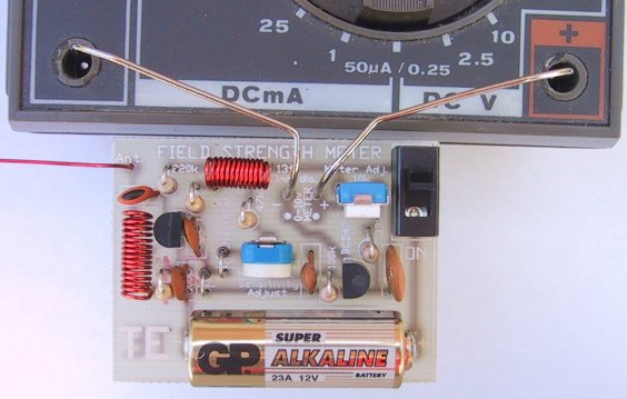
A close-up of the Field Strength
Meter MkI connected to a multimeter |
|
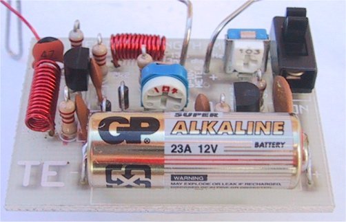
A close-up of the circuit Board showing the the position of the components |
|
Field Strength Meter MkI Circuit. A 2N2222A transistor can be used in either/both locations |
Up to now, field strength meters have only been able to detect
transmitters with an output of 100 milliwatts or higher, and for an output
such as this, a simple circuit such as a meter and a coil is sufficient. But
when it comes to a low power device, a simple circuit, with no amplification,
is not suitable.
We spent more than 5 days building all the circuits we could find - that purported to be suitable for low-power transmitters, hoping
to find one that would work.
Unfortunately none came anywhere near good enough so we had
to design our own.
The circuit we came up with is shown above and it
incorporates an RF amplifier, diode rectification, and a DC amplifier so that a
movement from a multimeter (a movement is the 'meter' part of a multimeter)
could be used as the readout. The heart of the design is a pair of diodes that
are partially turned on via a resistor (the 100k sensitivity control) and this
overcomes some of the .6v threshold of a diode.
You may not think .6v is very much but when you are talking in millivolt terms,
it is 600 millivolts. The signal we are attempting to pick up produces one or
two millivolts on the receiving antenna and if you need 600 millivolts to turn
a diode ON, the field strength meter becomes very insensitive.
Our design overcomes this problem and produces a reading up to 10cm from a bug.
This means you can adjust and peak a bug with the antenna fitted and get an
accurate indication of the power it is producing.
Up to now you have had to rely on the "LED Power Meter” as described in
a previous article and although it gives a good indication of the RF
energy, it does not take into account the loading effect of the antenna.
The antenna loads the output stage of any transmitter and when you have a low
power device, the antenna tends to detune the frequency slightly
so that a slight re-peaking is necessary if you want to get maximum
performance. The field strength meter will allow you to do this and get back
the extra performance you may have lost.
HOW THE CIRCUIT WORKS
The circuit consists basically of an RF amplifier, diode rectifier and a DC
amplifier. The first feature that may be new to you is the inductor in the
antenna circuit. You may think it produces a short-circuit between the antenna
and earth but the inductance of the 15 turn coil creates a voltage across it
when the antenna picks up a signal. This voltage is fed to the base of the
first transistor via a 47p capacitor and since the transistor is turned on via
a 220k resistor, any signal from the 47p will be amplified by the transistor.
The RF amplifier has been designed to only have a gain at high frequencies. In
our case this is at about 100MHz to 300MHz. The 300MHz is the upper limit due
to the response of the RF transistor and the lower frequency is governed by the
100p bypass capacitor on the emitter.
It's impedance at 100MHz is 16 ohms and this gives the stage a gain of about
12. At 10MHz the reactance of the capacitor is 160 ohms and the gain of the
stage drops to about 2.
This prevents low frequencies from being amplified and up-setting the reading.
By increasing the value of the emitter bypass capacitor, the gain of the stage
will be increased but this is not desirable as it may cause excessive gain
causing the front end to self-oscillate.
The inductor in the collector circuit separates the output signal from the
power rail and increases the output amplitude slightly.
The low value coupling capacitor (100p) between the RF stage and diode pair is
sufficient to transfer the energy as, don't forget, we are dealing with very
high frequencies. The two diodes in the diode stage simply work as a rectifier
and are partially forward biased via a 47k and 100k sensitivity control from
the positive rail. But they are not turned on fully due to the base emitter
junction of the DC amplifier transistor only allowing .6v to appear across
them.
When a signal is passed into the diode pair, the negative excursions
reduce the voltage across them and this begins to turn off the DC amplifier
transistor and thus the needle on the meter drops. It requires about 300mV
signal to start the process and with a gain of about 12 on the RF transistor,
we need about 30 millivolts developed on the antenna circuit to start the
detecting process.
This makes the Field Strength Meter only sensitive to nearby
signals and prevents weaker signals from upsetting the reading.
The 10k pot connected to one end of the voltmeter sets the full-scale
deflection for a 0-10v range on the multimeter.
The circuit consumes about
3.5mA and with a lighter battery (50mAHr cells) the circuit will operate for
more than 12 hours. A switch is provided to conserve the battery when not
required and the board attaches to any multimeter via leads and paper clips
that have been bent to suit the banana sockets on the meter.
Any old meter will do and it can have a sensitivity from 1k ohms per volt to
50k ohms per volt. The range we used in our prototype is 10v DC on a 30k ohms
per volt meter however 12v, 15v or even 25v scale will be ok and the 25v range
simply means the needle will not deflect as much, for the same RF detected.
You can even use an old, broken, multimeter providing the movement is not
damaged. We have about 5 of these field strength meters, one for each
worker, as everyone needs one to peak the devices we are making
We turned 5 broken multimeters into active service. It's one good way of using damaged equipment. It's amazing how the staff can blow up things, with the
ohms range not working and the milliamp range burnt out.
I remember one firm had the same problem. They made all the staff spend every Friday afternoon repairing the test equipment but with the tight
economics of today, we couldn't afford the luxury of providing half a day's
holiday like this each week.

|
Field Strength Meter Mk I Kit |
|
PARTS LIST |
|
2 - 2k2 1 - 33k 1 - 47k 1 - 100k 1 - 220k 1 - 47p ceramic 2 - 100pceramics (101) 1 - 22n ceramic (223) 1 - 100n ceramic (104) 1 - 10k mini trim-pot 1 - 100k mini trim-pot 1 - BC 547 transistor 1 - PN 3563 RF transistor 2 - 1N4148 diodes 1 - 13t enamelled wire 3mrn dia coil 1 - 15t enamelled wire 3mm dia coil 1 - 12v lighter battery 1 - 25cm enamelled wire 1 - SPDT mini slide switch 2 - paper clips 1 - FIELD STRENGTH METER PCB |
|
Extras: |
| 1 - multimeter (0v -10v range) |
|
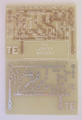
Field Strength Meter MkI PCB |
CONSTRUCTION
All the components, including the 12volt lighter battery and switch, mount on
the PC board. The legend on the board shows where each part is placed arid we
have found it important to avoid over-heating the diodes and transistors as
they lose their peak performance and cause the circuit to become very
insensitive. Follow the overlay on the PC board to see where everything is
placed. The coils are pre-wound in the kit and are wound on a 3mm diameter
Philips screwdriver (if you are making your own) and the wire size is not
critical as they simply form a broad-band trap.
The antenna wire is enamelled to prevent it touching the active components of
the bug you are testing.
We needn’t say any more about construction as you will obviously know how to
put the kit together.
SETTING UP
Solder the paper clips to the board as shown in the photo and bend them to suit
the sockets on the multimeter. Turn the "sensitivity" control (100k pot) to
minimum resistance and switch the circuit ON. Turn the "Set full scale
deflection" pot (10k) to give full deflection on the meter. Now turn the
sensitivity pot until the needle just starts to "dip."
At this point the circuit is the most sensitive as the DC amplifier transistor
is just turned on and any signal appearing on the diodes will reduce the
voltage appearing on the top of them and turn the transistor off - the needle
on the meter will begin to drop. The Field Strength Meter is now ready for use.
USING THE FIELD STRENGTH METER
This project will help you get the best silt of any transmitter. It will give
an accurate readout because it does not connect to the transmitter but
registers the strength of the field AT A DISTANCE.
The way it is used is to set up the antenna of the Field Strength Meter in the
same plane as the transmitting antenna (to get the best pick-up) and at a
distance that just causes the needle on the meter to deflect.
The meter is wired as a "DIP" meter and the needle deflects towards zero as the
field strength increases. Place the bug to be peaked on the test bench, with
the antenna out-stretched and bring the receiving antenna so that the needle just
starts to dip.
Peak the circuit a small amount and take your hands away so that they don't
upset the reading, and watch the needle. As the output increases, the needle
dips further. By maintaining the exact same distance between bug and meter, you
can compare one bug with another.
It's the fastest way of determining the output without doing a "field test."
IF IT DOESN'T WORK
As with all our projects, they work be cause we have actually built them and
checked their performance. If yours doesn't work, the first thing to do is
check the value of the components against the overlay on the board.
Two components in the wrong place can make a huge difference and a circuit like
this is fairly critical as the biasing must be correct.
Secondly, make sure all the parts are fitted and nothing has been missed. Also
make sure all the parts have been soldered neatly and cleanly.
We still get projects sent to us for repair where one or more leads have not
been soldered and obviously the project could never work.
Next you can make a few voltage readings. Although they don't tell you too
much, it is a fast way of determining if a stage has the correct DC conditions.
| The voltages: |
| RF Stage: |
| Collector:
6.1v Base: 5.8v Emitter: 5.2v |
| DC stage: |
| Collector:
0.2v Base: 0.65v Emitter: 0v |
If these check out ok, you should make a few further DC tests. If the meter
swings full scale at power-up, you should short between base and emitter of the
BC 547 to see the needle falls to zero. This will show the transistor is
working ok. If not, the transistor may be shorted.
Next remove the 47k on the diode pair. This will also cause the needle to move
down-scale and show the biasing network is working. It is more difficult to
test the RF stage and merely probing around the stage with a meter or CR0, will
pick up hum and cause the needle to deflect.
Of course we have assumed you have bought a kit and PC board for the project.
The frequency of operation of this circuit makes it important that it is built
on the correct PC board.
We cannot guarantee "breadboard" jobs or circuits made with your own components
as so many variables creep in.
Things like different markings on capacitors, different RF transistors or
signal diodes could make the difference between success and failure.
If you know what you are doing, that's fine - you can use your own components.
But if you intend to learn from our projects, don't take any chances. It's
cheaper in the long run to get all the projects in kit form and build them
exactly as specified.
If you get really stuck, don't hesitate to buy another kit and start again. You
can come back to the faulty one later. This project is so important that we
don't want you to miss out. With a field strength meter you can carry out
experiments that would take a chapter of a book to explain. Here's one:
EXPERIMENTING
Take the Voyager project and connect 30cm of tinned copper wire to the antenna
point on the PC board. Hold the Field Strength Meter in your hand (keep away
from the actual circuit by holding the multimeter) and bring the receiving
antenna near the Voyager antenna, without touching it. As you move up and down
the Voyager antenna, watch the needle.
It will show that energy is not radiated uniformly from the antenna but has a
maximum and minimum value. It is for you to see where these occur. Measure the
length of the antenna and plot the results. Cut 2cm off the antenna and repeat
the tests. Fit a 175cm antenna to the bug and repeat the tests.
This will give you a good understanding of the phenomenon of electromagnetic
radiation.
There are lots of other things you can test with this project.
The Field Strength Meter Mkll is presented in the next article and has the
advantage of a tuned front end and 3-LED readout. This will enable you to not
only peak transmitters but also find the frequency on which they are operating.
It detects in the range 75MHz to 140MHz enabling you to design and build
transmitters capable of transmitting off the normal broadcast band.
But don't put off building this project as you will need both of them as they
have different capabilities. And you also need the LED Power Meter.
Test equipment is very important when working with RF so don't put it off any
longer, start now and build up your range of gear.