|
Jim's Crossing Lights MkIV |
|
Built and tested
module $20.00 |
This project operates crossing lights automatically, before the train enters the crossing and turns them off automatically. The flash-rate can be adjusted as well as the brightness of the lights and the overall length of time for the flashing. No other module on the web offers these features.
Two LEDs on the module indicate when the lights are flashing and the module comes with 4 extra LEDs for those who have bought crossing signals without the LEDs installed.
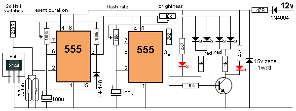
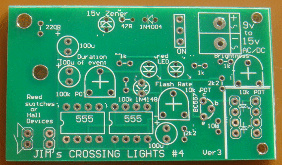
The circuit has a number of very clever features.
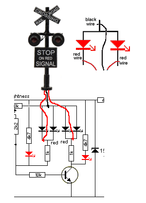
It uses two 555 ICs to provide all the functions. The signal diode on
the first 100u discharges the 100u quickly when the circuit turns off so
the timing can restart with full duration.
The flash-rate can be adjusted because everyone says "the flash-rate is
not right."
The "duration of the event" can be adjusted to suit your layout.
The brightness of the LEDs can be adjusted to suit the type you are
using.
The circuit will take 12v DC as the ideal voltage. Do not go below 10v
DC as the voltage drops across the various components gives the second
555 less than 5v because the power diode drops 0.7v, the 47R drops about
1.5v and the first 555 outputs a voltage and current via pins 3 to the
second 555 for all the rest of the circuit. There is about another 1.7v
drop in doing this.
The circuit will work perfectly up to 15v DC and when you supply a DC
voltage higher than 15v, the 15v zener comes into action and any voltage
above 15v, will be dropped across the 47R resistor. If your supply 16v,
the voltage drop across the resistor will be 1v and the current that
will flow through the 47R will be
The zener in this circuit is NOT called a zener regulator but a ZENER LIMITER. It prevents voltages higher than 15v because the 555 IC's are limited to 18v operation.
The circuit is designed to take either two reed switches OR two Hall effect devices (switches).
The Hall switches are connected in a very clever way. They are connected so that they sit with a load resistor of 220R and due to the small current they require, the voltage at the "pick-off" point is about 9v for a 12v supply.
When any of the input devices detects magnetic flux, they close or produce a fairly low resistance, in the case of the Hall devices and the circuit switches ON. The voltage goes to 0v for the reed switch, but the Hall device is different. When it detects magnetic flux, the output transistor turns ON an this "pulls" the "pick-off" point lower and as it gets lower, the voltage to the Hall device drops too. As the voltage across the device reduces, its capability to keep the output low is reduced and thus the output does not drop to 0v, but stops at about 2-3v. At this voltage the device is still working and pulling the output as low as possible, (with the current that is available at this low voltage). This is sufficient for the 555 to detect a LOW.
You can combine one reed and one Hall device as the 220R will cover the requirement of either/both devices.
The voltage at the "pick-off" point is detected by Pin2 of the 555. This pin only detects a LOW and when the voltage drops to 33% (or less) of the voltage on pin 8 of the chip, it starts to "time the event."
The timing of the event is done by charging a 100u via a resistor(s) and when Pin6 detects 66% of the voltage on the Pin8, the output Pin 3 goes HIGH and the project turns OFF. The only component taking current when the project is not flashing, is the first 555 and this takes up to 10mA.
To reduce the brightness of high-bright red LEDs, it takes up to 10k via a mini trim pot. This will allow all different types of LEDs to be used.
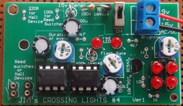
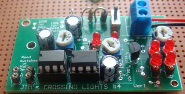
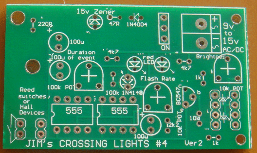
Ver1 had a track missing and ver2 is the corrected version
The load for the reed switch and Hall device is now 220R
This PCB is designed for "Type-A" lights
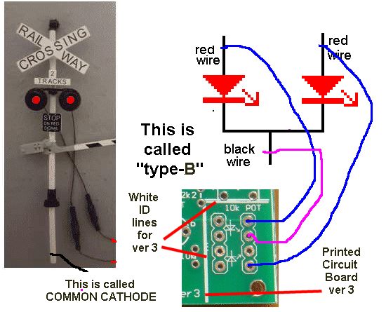
ver3 is designed for "Type-B" lights
Reed Switch Vs Hall Device
In this project, the operation (the detecting range) of the Reed Switch
is about 10mm.
The detecting range for the Hall device is 4-6mm
The Hall device is much smaller.
These are the only differences and you can decide which you want for
your layout.
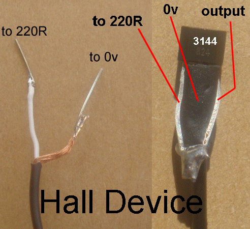
The Hall Device must be connected the right way to the circuit.
Here is a close-up the Hall device with the output lead connected to the
first lead. These two are connected to the white lead of the screened
audio cable. The middle wire is the ground connection and it goes to the
screening wires.
Connecting the screened lead to
the Hall device
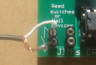
Connecting the Hall wires to the
module
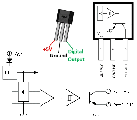
The internal circuit of the 3144
contains a number of "Building Blocks"
The Hall device is being used in an unusual
way in this project, with the output connected to the "supply terminal."
The circuit above shows some of the "building blocks" inside the 3144
and one of the features is the amplifier block that detects a signal
from the Hall block to turn ON the output transistor. Some
of the other Hall devices turn-on-slowly as a magnet is brought closer
to the detecting face. Make sure you do not use one with this feature,
as we have not checked it and it may not turn on hard enough to start
the module flashing. The main reason for it not working is the low
impedance of the input line due to the 220R load resistor.
THE REED SWITCH
You may find the Reed Switch is "polarised." This
simply means the reeds contain some residual magnetism and when you
bring the north pole of a magnet towards the switch, it will only be
detected at one end.
That's why you have to lay the switch "in-line" with the rails so the
magnet will definitely activate the switch as the train passes over.
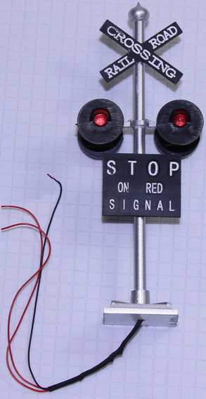
The MODULE
Jim's Crossing Lights module is available fully-built for $25.00 and only needs to be connected to
12v DC. Connect the reed switches or Hall devices to the input terminals
and switch ON.
Bring a magnet up to the reed switch or Hall device and work out the
distance at which it is detected.
The magnet must be around the correct way for the Hall device as it
detects just the North or South pole, according to the way the Hall
device is placed and which side of the Hall Device you are using.
The detection range is about 5mm for the tiny super-magnets we supply in
the kit
Place the reed switch or Hall device in the centre of
the track and hold it in place with glue. Glue the magnet under the loco, and have the gap
between the magnet and Hall device small
enough to make sure the circuit responds every time.
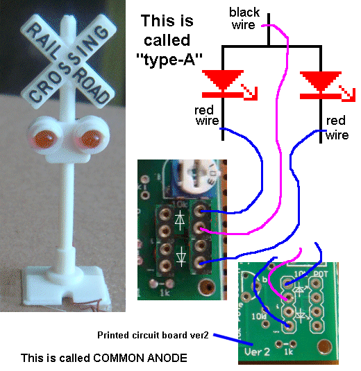
CROSSING LIGHTS
There are many different types of crossing lights and most of them have
three wires.
The black and red wires are shown in the diagram below. Technically
speaking, the anodes are connected together and emerge via a black wire.
This wire can sometimes have a resistor connected to it and enclosed in
heatshrink. You need to remove this resistor as Jim's module has current
limiting resistors. The other two wires are generally red and are the
cathodes of the LEDs.
You can see the drawings on the PCB correspond to the symbols for the
two LEDs. The two middle holes are available when each LED has separate
wires.
The Crossing Light above is
available from Talking Electronics for $5.00
You will need 2 of these. (HO scale)
COMMON ANODE -
most popular
This crossing Light is on eBay
The black wire goes to the positive and the red wires to negative
(via resistors) - This is TYPE-A
It is called COMMON ANODE and is the
most popular type
Wiring TYPE-A Crossing Lights
COMMON ANODE
The diagram above shows how the crossing lights are wired to the PC board ver3 when the black and two red wires are inserted into the socket on the module. If the lights have a resistor in the black lead, this can be removed as the module has current-limiting resistors. The 4 test LEDs on the module are removed so you can fit your lights.
CHECK YOUR LIGHTS
Before buying this project, you need to check the type of CROSSING
LIGHTS you will be connecting to the module.
There are two DIFFERENT types and the wrong type will not work.
That's why we have two different modules.
Don't worry about the make, model or style or how many resistors or the
colour of the leads on your Crossing Lights. You have to work out if the LEDs are wired as
TYPE-A or TYPE-B.
A single wire to the
positive is TYPE-A - suitable for the module above - Type-A
A single wire to the negative is TYPE-B - order this module as Type-B
This is how you do it:
TYPE-A
Get a 9v battery and place it as shown in
the diagram with the positive terminal as shown.
Now find the wire that connects to both LEDs and connect a 470R safety
resistor and connect it to the positive terminal. Now get the other wires and connect
them to the negative
terminal of the battery and the LEDs will illuminate.
Don't worry about the colour of the wires. If both LEDs illuminate as
shown in the diagram, you have type-A:
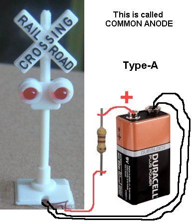
A single wire to the positive is
TYPE-A
COMMON ANODE
TYPE-B
Get a 9v battery and place it as shown in
the diagram below with the positive terminal as shown.
Now find the wire that connects to both LEDs and connect it to the negative
terminal of the battery.
If your Crossing Lights do not have any resistors hidden in the leads,
you will need to add a 470R safety resistor to prevent the LEDs being
damaged. Now get the other two wires and connect them to the positive
terminal of the battery and the LEDs will illuminate.
Don't worry about the colour of the wires. If both LEDs illuminate as
shown in the diagram, you have type-B:
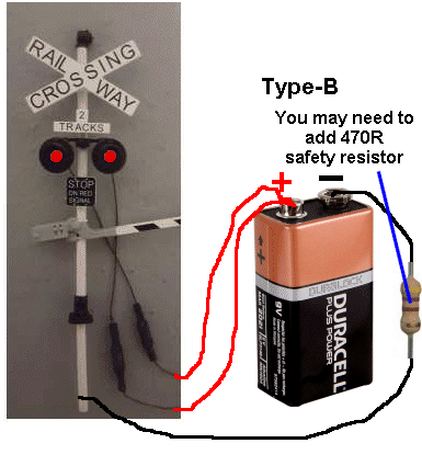
A single wire to the negative is TYPE-B
COMMON CATHODE - less popular
The project described above uses TYPE-A
CROSSING LIGHTS with ver2 PCB and TYPE-B CROSSING LIGHTS with ver3 PCB.
If you have CROSSING LIGHTS TYPE-B, you need to order JIM'S
CROSSING LIGHTS MkIV Type-B
I emphasize this 15 times because it is so simple to get it wrong. Check
your lights with a 470R resistor on every lead (three 470R resistors) to
start with and nothing will be damaged. The LEDs will be dull but none
of them will be damaged.
Do the test 3 times and prove the type of lights you are using.
Now order the kit or the fully built and tested module.
|
Jim's
Crossing Lights |
|
1 - 47R all 0.25watt 1 - 220R 2 - 1k 1 - 2k2 2 - 4k7 1 - 10k 1 - 100k 2 - 10k mini trim pots 1 - 100k mini trim pot 3 - 100u electrolytics 1 - 1N4148 diode 1 - 1N4004 diode 1 - 15v 1watt zener diode 6 - 3mm red LEDs 2 - 555 ICs 2 - 8 pin IC socket 1 - BC547 transistor 2m - 2-core cable for input devices 2 - mini reed switches or 2 -- Hall effect devices - 3144 2 - 10mm diam x 1mm super-magnets 1 - 2-screw terminal block 2 - 2 pin sockets - round pins 2 - 4 pin sockets - round pins (called machine pins) 1 - mini slide switch 1 - 20cm very fine solder 1 - Jim's Crossing Lights MkIV PCB Type-A ask for Type-B You will need 2 x Crossing Lights as shown in the images above - and work out if Type-A or Type-B - so you get the right module |
2/5/2019