|
KATO |
|
|
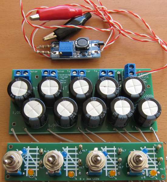
This project
controls up to 4 Kato points
All solenoid point controllers consist of a coil of wire - called a SOLENOID - and an actuator or arm or plunger that goes down the centre of the coil.
If the rod is made of soft iron, it is not a magnet, but can be attracted to an electro-magnetic field and when the current is turned off, the rod does not hold any magnetism.
With this type of solenoid, it is called a PULL SOLENOID and the rod is pulled into the coil.
If the rod is a magnet, it will be pulled into the coil when the supply is connected around the right way and when the supply is reversed, the rod will be pushed out of the solenoid.
This is the type of solenoid used in the KATO POINT MOTOR and that's why it has 2 wires.
When the voltage is in one direction, the solenoid pulls the rod and when the supply is reversed, the solenoid pushes the rod.
This is called ELECTRO-MAGNETIC-INTERACTION.
The other thing to know with this type of solenoid is the TIME OF OPERATION.
The power must be applied for a very short period of time to prevent to solenoid getting hot.
It it gets hot, the plastic melts and the actuating arm freezes.
To prevent this, the KATO control switches are called PASSING SWITCHES and only deliver a current when the switch is in the centre of its travel.
But if the switch is not operated fully, the solenoid will burn out.
These switches are very large and expensive.
We have produced a cheaper alternative and 100% incapable of heating the solenoid. The module also has indicator LEDs to show the position of the point.
|
INSTRUCTIONS Connect the supply to the terminals at the end of the module. The Supply can be a Plug Pack (wall wart) or from your train transformer. It can be AC or DC. The AC wires can be connected either way around. The DC wires will not work if connected the wrong way. The module will work with voltages in the range 10v AC to 12v AC or 12v DC to 15v DC Connect the Kato Point Motor to the terminals at the top of the module with the wires either way around. If the Point Motor "bangs" too hard in each direction, you can reduce the voltage. |
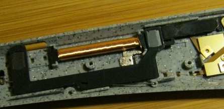
The KATO solenoid
The solenoid is long and thin but this is just a bad
design as the pulling of the rod only takes place between the tip of the
rod and the turns in front of the rod.
The rod only moves 2cm and that's the only active part of the
wiring. If the magnet is short, only each end will be acted upon.
There are little or no magnetic lines of force down the sides of the
magnet and thus the magnetic force produced by the coil in
this section have NO EFFECT.
The next thing to consider is the amount of energy required for the
solenoid to activate the point.
The project has 2,000 microfarad and the actual energy it will deliver, depends
on the voltage on the electrolytic.
You can adjust the power of the solenoid by either using just 1,000u or
reducing the voltage.
Reducing the voltage has a very big effect as half the voltage will
deliver 25% of the energy.
You can test the amount of energy needed by reducing the voltage until
the action is not reliable and then increasing it 3v for perfect
reliability.
The KATO Point Motor
Circuit
The CIRCUIT
The circuit is very simple. The
electrolytic is charged when the toggle switch is in the "down position"
and the charging current flows through the solenoid from the supply to
the electro.
This makes it change the point to the siding.
When the switch is in the "up position," the energy in the electrolytic
flows out and through the solenoid, from the lower wire to the wire
connected to the supply. This is in the opposite direction to previously
and is actually a VOLTAGE REVERSAL. And because the voltage is reversed,
the current flows in the opposite direction.
This activates the solenoid in the opposite direction and the point
changes to the main line.
This very simple circuit does TWO THINGS. It supplies a pulse of energy so
the solenoid does not get hot
and creates a voltage reversal so the solenoid activates in both
directions.
The LEDs on the board show the position of the point.
The power diode does two things. It allows AC to be connected and
although only the positive cycles charge the 1,000u electrolytic, this
is sufficient for the circuit to operate perfectly. The diode also
prevents DC connection around the wrong way. DC around the wrong way
will not illuminate the LEDs and the 2,000u will leak when voltage is
applied in the wrong direction and not charge properly.
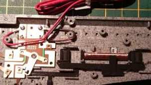
Connecting the
Kato points to the module
New PCB's have 2 x 1,000u in
power supply (10 electros on board)
| |
|
10/3/2022