MkIIb
WITH SLOW DOWN
A REALISTIC DICE WITH “TUMBLING" ACTION
Mods to circuit at end of article
![]()
These combine to make it one of our most popular games projects.
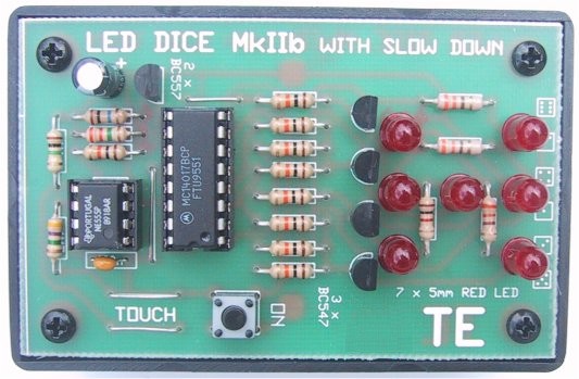
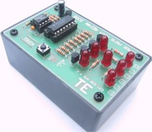
As can been seen in the photo, the 7 LEDs are positioned on the board in the same positions as the spots on a dice (die). When these are activated, they simulate the rolling of a real dice as it rolls across the table.
Consequently we have called the project LED DICE WITH SLOW DOWN.
The whole project fits neatly on top of a medium sized Zippy box with the printed circuit board mounted in place of the aluminium lid. It's another one of our projects that you will be pleased to show around.
A small pre-printed panel can be placed under the LEDs before soldering and this will add to the realism of the project.
Since the LEDs have a low level of illumination. they may be lost in bright sunlight but in a normally lit room, they will be very effective.
All the parts for this project are readily available and the best way to get everything is to buy a kit. The only parts not included in a kit are the Zippy box and 9v battery.
|
The LED Dice fitted onto a project box with the battery inside |
|
LED Dice MkIIb with slow down circuit |
HOW THE CIRCUIT WORKS
The way the circuit works is very ingenious. When you touch the TOUCH PLATE wires, the LEDs start flashing in a similar manner to a dice rolling over and over. This gradually slows down to rest and a number is displayed exactly like the spots on a dice.
This "illuminated dice" effect has fascinated me ever since I saw it on a billboard near a busy city junction.
It showed a pair of brightly lit dice tumbling over and over and finally coming to rest on a randomly selected number. An apt caption below the sign read: "DON'T GAMBLE: USE SHELL.
Unfortunately the sign was pulled down to make way for road widening and I don't think it has appeared elsewhere.
In those days, whenever I passed the sign. I had a personal bet as to which number would come up next. I don't think I ever won, even though the chances were just 36:1.
With the passage of 20 years, the mechanics and electronics of the display can be reduced to a couple of IC's and a handful of parts. I hesitate to think how many switches and relays were used in the original sign.
As I mentioned, the operation of the circuit is quite ingenious. We have programmed the first six outputs of a DECADE COUNTER to light various combinations of LEDs. These LEDs are arranged at one end of the PC board to form the dot layout of a normal dice. One extra LED is placed in the centre to create the pattern for 'one,' 'three" and 'five'.
Instead of sequencing each output to correspond to one, two, three, four, five etc on a dice, we have jumbled up the sequence to simulate the rolling of a real dice.
The first unusual feature you will notice with the circuit is output pin 2. It seems to go nowhere. Only after examining the make-up of the numbers 1, 2, 3, 4, 5, and 6 will you notice that the LEDs representing the number 2 are also used for 3, 4, 5, and 6. The only time when they are extinguished is for the number 1. We have used this fact to reduce the number of components.
The next important feature involves the buffer transistors. They are necessary to drive the LEDs adequately to obtain maximum brightness. We found it unsuccessful to drive the LEDs directly from the outputs of the CD 4017, especially with the gating circuitry needed.
The 10k resistors have a dual function. They are used for gating and also as current limiting for the base of each transistor.
Take pin 1 of the CD 4017 for instance. When it is HIGH, it will turn off the upper BC 557 transistor and also turn on the transistor driving LED 4. Also connected to pin 1 is a network of 10k resistors that produce a voltage dividing effect on the voltage to the base of the transistor driving LED 4. Since a transistor requires only about .6v, to turn it on, we have plenty of reserve in the arrangement shown.
When output pin 2 goes HIGH, the only LEDs to be illuminated will be 2 and 6. This represents the number 2 on the dice.
The rest of the circuit is fairly straight-forward. It comprises two building blocks: a 555 oscillator and a transistor slow-down circuit.
|
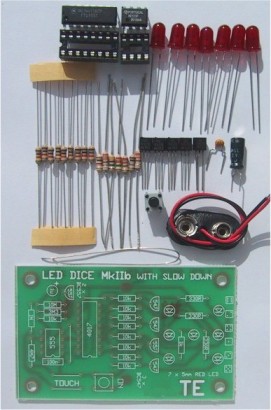
LED Dice kit of components |
|
PARTS LIST |
|
3 - 330R resistors 1 - 1k 9 - 10k 1 - 1M 1 - 3M3 1 - 4M7 1 - 10M 1 - 100n capacitor 1 - 1u 16v electrolytic 3 - BC 547 transistors 2 - BC 557 1 - 555 IC 1 - CD4017 IC 7 - 5mm Red LEDs 1 - PCB mount push button 1 - 8 pin IC socket 1 - 16 pin IC socket 10cm tin copper wire 1 - battery snap 1 - PC board LED DICE WITH SLOW DOWN |
MOUNTING THE PARTS
The printed circuit board has been designed to fit exactly on top of a UB3 Zippy or Jiffy box. The corner holes take self-tapping screws that fit into the moulded pillars.
All that will be housed inside the box is a 9v battery.
Before soldering any components, make sure the board fits neatly over the opening. Trim the sides of the board with a fine file or sand-paper to give it a neat fit. Open out the four corner holes to take self-tapers.
Begin construction by mounting the resistors, capacitors and transistors. Note that a BC 557 fits between the set of BC 547 transistors. You will also need to take care when inserting the LEDs. All the cathodes face one direction except ONE. LED 2 is positioned around the other way. Everything else is as shown on the overlay of the printed circuit board.
All the components on the board are neatly laid out and not cramped. The TOUCH PLATE consists of two parallel wires fitted over the top of the board like two staples. The on/off switch can be either a press switch or a single pole toggle switch. If a push-button is used, it can be used to clock the 4017 to show a random number without having to wait for the slow-down.
The IC's are the last items to be fitted. Use sockets to mount them. This is our policy for all projects. Not only does it prevent damage to the chip but you can remove a chip at any time and test other chips in the socket.
Finish assembly with a battery snap and clip it onto a 9v battery.
Drag out your old MONOPOLY game. This LED DICE will add new enthusiasm to playing the game. It may even bring you good luck!
TESTING THE UNIT
Connect the battery and you should see a number of LEDs light up. Place your finger on the TOUCH PLATE and all the LEDs will appear to be lit. They will gradually slow down to a flicker and finally come to rest. This is the correct action for the project but sometimes things don't work out quite so simply.
There are three possible areas for faults to develop:
1. The slow-down section.
2. The oscillator section.
3. The counter and readout section.
Without any test equipment it is only possible to test these three sections by starting at the display end and working back to the slowdown stage.
If the LEDs do not begin to flash when you touch the TOUCH PLATE, you will need to isolate the fault by removing pin 3 of the oscillator from the input of the 4017. This can be done by removing the 555 or cutting the track. Manually clock the IC by tapping a 10k resistor from the positive rail to the input line of the chip. This should make the LEDs change from one state to another.
Next re-connect the 555 and bridge Q1, the slow-down transistor, with a 10k resistor between collector and emitter. This will make the BC 557 transistor. Clock the counter fairly quickly. If this does not happen, check the 555 and the 100n capacitor.
To test the slow-down circuit, short the two TOUCH PLATES together with a wire link to produce a very fast-changing display. If this has no effect, check the BC 557 and its surrounding components.
If one or more LEDs do not light up, check the way they are inserted or swap them with another LED that is lighting up.
With this method you will "home-in" on the fault.
MODIFICATIONS
One reader had problems with LEDs "2 and 6." They did not go off. This was due to the output voltage of 4017. When pin 1 was HIGH, the voltage on the pin was about 1.5v lower than rail voltage. The data sheet states the HIGH output should be 50mV lower than rail, not 1,500mV!
Something was wrong!
The solution was to add a "voltage divider" resistor on the base to produce a voltage between base and emitter that is less than 500mV so the transistor turns off. The following circuit shows the additional resistor: