
A game of skill
LED Zeppelin is a game of patience. It's like getting a kite into the air.
It goes up slowly but the slightest mistake will bring it down like a lead
balloon.
![]()
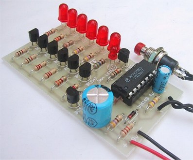
The association fits perfectly. The game consists of six LEDs and an indicator LED that flashes at a rate of about 2 cycles per second. A push button is the "Operations Control" and by carefully pushing the button in synchronisation with the flashing LED, the row of LEDs will gradually light up.
But the slightest mistake will immediately extinguish one, two or three LEDs. The aim of the game is to illuminate the 6 LEDs with the least number of pushes.
|
A close up of the completed LED Zeppelin |
|
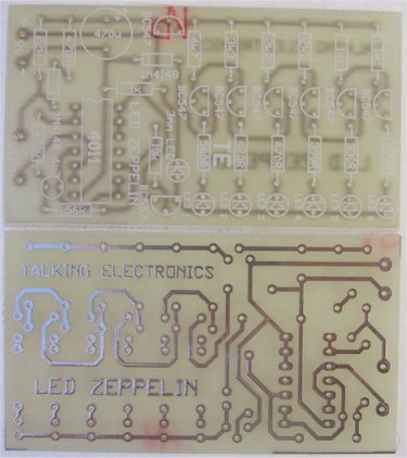
LED Zeppelin Circuit |
HOW THE CIRCUIT WORKS
The circuit consists of a three-inverter CMOS clock-oscillator driving Q8 that flashes the LEDs on and off. The other output from the oscillator is used to charge up the 470u electrolytic C2, via R3.
The output from pin 3 is in the form of a square wave only slightly less than the supply voltage and is about 7.5v to 8v in amplitude. The frequency at which the circuit works is governed by R1, R2 and C1 and is approximately 2Hz. Charging of the 470u electrolytic is exponential so that initially the voltage increments on the capacitor will be high when it is beginning to charge. Each time the button is pressed a small amount of energy is fed into C2. This voltage appears at the base of Q1. Q1 is connected as an emitter-follower and the same value of voltage will appear at the emitter, less 0.6v base-emitter voltage drop.
This voltage is then fed to the base of six transistors Q2 to Q7 that drive LEDs 1-6 via current limiting resistors. Each of these transistors will turn on according to the voltage on the 470u electrolytic.
When the voltage rises to 0.6v, Q1 will turn on. For Q2 to turn on its base must be .6v higher than the emitter. Q2 has a forward-biased diode in its emitter and the voltage drop across it will be .6v. The base of Q2 must be .6v above the emitter, making it .6v plus .6v or 1.2v This means the voltage on C2 will be .6v plus .6v plus .6v or 1.8v for the first LED to be fully lit.
The emitter of Q3 is connected to the base of Q2 so that a further .6v will turn it on. At each successive .6v rise the next transistor in the chain will turn on until finally Q7 will turn on. This transistor drives the top LED that is the highlight of the game. When you have LED 6 pulsing you really feel a sense of achievement.
Should the button be pressed when the oscillator is low, diode D1 is forward biased and the charge on C2 will rapidly discharge through R4. Since the voltage increments become smaller as the 470u becomes fully charged, to light the top LED requires significantly more pushes than LEDs 1 and 2.
If, however, the button is pushed too long, the discharge will be greatest when the capacitor is nearing full charge and an error here will lose the gain made by many pushes. This is where the skill of the game comes in. The charging of the capacitor is "out of phase" with the flashing of the LEDs. This means the button must be pressed when the LEDs are extinguished. To turn the game off or restart it, push the button when the LEDs are lit. This will remove the charge on C2 and eventually every LED will go out.
TERMINOLOGY
Some of the terms used in our articles may be new to some readers.
We have used universally recognised symbols and standard component identification.
The letters LED stand for Light Emitting Diode.
A small LED is 3mm or 1/8", a large LED is 5mm or 1/4".
Most of the circuits in our projects use a general purpose NPN transistor. We have specified BC 547 or 2N 3904 or 2N 2222 for this, however there are many other types that will work equally well.
For the PNP general purpose transistor we have specified BC 557 or 2N 3906, however there are many other equally suitable types too. When we specify this type of transistor we also infer its characteristics are not important. It is very frustrating to find on odd type of transistor specified in a project. You immediately think it has special characteristics and start searching through catalogues for a supplier. Most battery-operated projects use the most-common cheapest, transistor available in your country.
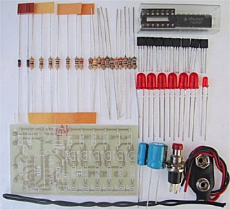
| LED Zepplin kit |
|
PARTS LIST |
|
1 - 270R 1 - 330R 1 - 390R 3 - 470R 3 - 1k 2 - 2k2 1 - 3k3 1 - 4k7 1 - 10k 1 - 22k 1 - 56k 1 - 470k 1 - 4u7 16v PC mount electrolytic 1 - 470u 16v PC mount electrolytic 7 - BC 547, or 2N 2222 transistors 1 - BC 557 or 2N 3906 transistor 1 - CD4011 IC 1 - 3mm (1/8") red LED 6 - 5mm (1/4") red LEDs 2 - 1N 4148 signal diodes 1 - 14 pin IC socket 1 - push button 1 - battery snap 1 - LED Zeppelin PC board |
CONSTRUCTION
All the components are mounted on the Printed Circuit Board. Follow the
layout diagram for the identification of each part. You will notice all the
components are placed neatly on the board with Q2 - Q7 fitted the same way
around and all LEDs the same way. For the transistors, the overlay shows
the shape of the case and this allows it to be fitted only one way
around. This only refers to BC 547. Refer to the transistor pinout for other
types.
Both electrolytics are identified with their positive lead on the overlay.
This lead is the longer of the two leads on a single-ended electrolytic and if
both leads have been cut the same length, you will have to refer to the stripe
on the side of the case for the negative lead.
The IC socket is next and is fitted so that the cut-out
at the end of the socket goes over the shape on the overlay.
The IC is inserted into the IC socket so that the cut-out at the end of the
chip fits over the cut-out at the end of the socket.
The last two items to connect are the two wires for the game-switch and the
battery snap. Check all soldering and the orientation of the transistors. It is
a wise to connect a milliammeter in one battery lead before switching on a project
for the first time to check if a short-circuit is present or excessive current
is being drawn.
HOW TO PLAY
The 3mm (1/8") LED begins to flash when the battery is connected. This
indicates the flash rate. To start the staircase of LEDS flashing, push the
switch a number of times, (when the LED is extinguished). After a few pushes you
will see the first LED flash faintly. Keep in step with the off periods and you
will gradually increase the illumination. The rest is up to you.
The LED ZEPPELIN game can be played a number of ways. The most popular way
is to count the number of pushes required to get the top LED flashing with
reasonable brightness. The player with the least number of pushes wins.
Another variation is to cover the six LEDs with black tape leaving just the
indicator LED flashing. The object of the game is to see how many LEDS can be
set flashing with a certain number of pushes. Start with 50 pushes per player.
Push the button 50 times then remove the tape and read your score. You can make
certain adjustments such as 3.5 or just over two LEDs flashing.
When used competitively like this, the game provides a means of assessing
your reflex time and co-ordination.