|
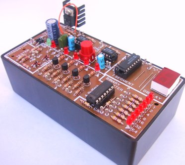
The Logic Designer circuit
diagram.
To keep the circuit diagram
uncluttered, we have omitted R1....R36 and C1...C4.
Parts should be located by reference to IC pin Nos or
transistor leads.
Do NOT change
the voltage-tap when the power is ON. It will cause over 18v to appear on
the power rail!
| 
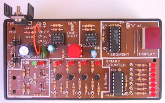
The 7805 voltage regulator pinout
WHAT DOES THE LOGIC DESIGNER DO?
The logic designer is filled with features. It would not be possible to list
all the possible combinations of the unit as the various building blocks on the
board can be interconnected to obtain a wide variety of counting and testing
stages. You will be able to see what we mean after you build the project and
start to interconnect the blocks yourself.
But we can give an outline of some of the features we have specially
incorporated into the board. You can consider the DESIGNER as a piece of test
equipment. It is specially designed for testing digital circuits. In fact it
will only test digital circuits. So don't expect to get any results from an
audio amplifier or radio. The type of digital circuits we are interested in
have presented in the pages of this e-magazine and with this tester you will
be able to detect the logic levels at 4 different points on a particular
project, at the same time. This
is very handy when you are attempting to locate a HIGH on the output of a
decade counter such as a CD 401 7. With its 10 outputs sequencing in a rather
awkward order of 3, 2, 4, 7, 10, 1, 5, 6, 9, 11, it would be handy to connect
up the outputs and read them off in a logical order. This you can do with the 4
buffered HlGH detectors on the DESIGNER.
Or take the situation where one delay
circuit is to trip the next circuit and finally gate a counting circuit. Here
you can use two of the buffer detectors and either the decade counter or the
binary counter to get a readout. You will then be able to compare the tally of
the project under test with the LOGIC DESIGNER tally.
The "one-shot" is especially useful for pulsing a circuit. Since it is fully
de-bounced, it will produce a clean pulse to clock any digital counting
circuit, just ONE count. And there is no chance of it giving two quick pulses.
The 555 has a delay of about 0.1 seconds so the maximum repetition rate is
10Hz, but the output does not change until the button is released. You will not
be able to achieve 10Hz manually. If you wish to clock a
circuit at 10Hz, the 10Hz clock is available. This can be divided down
to one of eight slower frequencies via the binary counter chip. As I said, it
is not until you get into it yourself that you will understand the full range
of possibilities for this piece of equipment.
All the components come properly packed and the IC's are protected in either foam or an IC sleeve. When you take them
out, don't throw the IC's in with the other components because the
static electricity may damage them. Always keep them protected and don't
handle them unnecessarily. Once they are fitted into IC sockets, they are quite
safe and robust.
FEATURES OF THE LOGIC DESIGNER
1. AC power
2. Battery power
3. 1.5 amp in-built power supply
4. 'One-Shot'
5. 10Hz clock
6. Divide by 10
7. 0 - 9 counter
8. Transistor Tester
9. 4 Buffer Amplifiers
10. Binary counter
1. An in-built fully-regulated power supply using a 3-terminal regulator
to supply 5v to 12v @ 1 amp.
2. The availability of using almost any power transformer from 6v @
100mA to 18v @ 2 amps to supply the LOGIC DESIGNER as well as some to spare for
any external circuit being constructed.
3. Battery operation: 6v to 12v.
4. A "one-shot" circuit with 300mA capability using a 555 to clock an
external counting circuit. The push-button is fully debounced and has a maximum
repetition rate of 10Hz.
5. A 10Hz clock using a 555 to give good driving facility to any circuit
you are designing.
6. A decade divider provided by a CD 4026 to give a 5Hz or 1 Hz clock
rate.
7. A 0 - 9 counter using a CD 4026 and a FND 500 7-segment display. This
must have a noise-free high-amplitude input signal to give an accurate readout.
8. A transistor tester to test all those unknown PNP or NPN transistors.
You will be able to find out their correct lead configuration, their polarity
and the fact that they do actually work.
9. Four buffer amplifiers to detect HIGH pulses on digital circuits.
This will save you trying to find 4 multimeters.
10. A binary counter reading up to 128. This will teach you binary
readouts and give you the availability of frequency division by 2, 4, 8, 16,
32, and 64.
By combining two or more of these features you will be able to create your own
detection circuits, frequency dividing circuits and counting circuits. The
scope is enormous and it will take but a few moments of experimenting for you
to really become familiar with the possibilities.
To:
Page 2

|