|
MECHANICAL TV |
|
|
This project is
a copy of the first TV. It was mechanical and it was an amazing achievement in the early 1920's, before the days of
the transistor and just at the beginning of the development of the valve
and the cathode ray tube (known as the TV tube or CRT). Unfortunately
John Logie Baird
preferred a mechanical means of producing a picture while the fully
electronic path (the CRT path)
was being developed by other inventors. In 1935 a public demonstration of
Baird's 240 line mechanical TV was compared with Marconi's far-superior
all-electronic system and in 1937 Baird's system was dropped. The
electronic system was FAR SUPERIOR.
The actual operation of the mechanical receiver is very simple but has not been
explained on any website or in any article at a level that will make it
clear to the newcomer. That's why we have produced this project. It
copies the earliest mechanical design and produces an image via an illuminated screen behind a spinning
disk containing small holes.
HOW DOES IT WORK?
For a start, you have to realise the picture on these early TV's was
very small, about to size of a postage stamp. It was increased slightly
by looking through a magnifying lens.
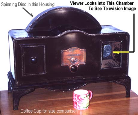
Here is a photo of the 1929 mechanical TV:
Here is an animation of an actual-size picture produced by the mechanical TV:
![]()
You can see the image is
very primitive but it represented an enormous advancement at the time.
Only a few years before, when the telephone was first demonstrated,
skeptics were looking at the wires to see if they were hollow, as the
voice must be travelling down the middle! Then came the miracle of radio
and now a "Moving picture" through the air-waves. We take all these
things for granted, but the thought of something as heavy as an airplane
flying through the air was an impossibility just a few years before. The
1880's to 1930's was the era of inventions, with the camera, movies,
cars, light, trains, electricity, radio, aeroplane, valve, etc etc etc.
(the transistor was still to be invented). Mechanical TV was truly an
achievement.
This is how it works.
A lamp is placed behind a spinning disk. The following photo shows the
back of the TV and the disk with 60 holes. These holes start near the
outside of the disk and gradually move towards the centre. You can see
the start and finish. The distance (the "rise") between the
finish and the start is the height of the picture. It is only the height of a postage
stamp. The width of the picture is shown above.
The disk is called a Nipkov
Disk, after its inventor and is shown in simplified form below. As the
disk spins, a small hole in the disk passes a window (shown curved).
Behind the disk is a lamp. The secret of the process is this: The lamp
must be able to be turned on and off very quickly. You cannot use an
ordinary filament lamp for this. It does not turn on and off fast enough.
That's why they had to use a neon lamp.
As the disk spins in a clockwise direction, the lamp is turned on for a
very short period of time such as when the hole is at say 12 o'clock.
This will produce a spot of light at this position. If the lamp is
turned on slightly before top-dead-centre and for a longer period of
time, a small arc will be produced.
If the lamp is turned on for the whole time the hole passes the window,
a full arc will be produced.
If the lamp is turned on before the centre, then off then on again, two
separate arcs will be produced.
In this way a single hole will produce all sorts of different patterns
across the top of the screen. If you can turn the lamp on and off 30
times, it will produce a resolution of 30 pixels - 15 "on" pixels and 15
"off" pixels. And this is exactly what the TV was capable of doing.
As soon as the hole leaves the window, the next hole is slightly down
the screen and in fact it overlaps the previous hole so there is no gap.
If there are 60 holes, the picture will be 30 pixels wide x 60 pixels
high.
If the lamp can be turned on slightly, the shade of the pixel will
change to give varying levels of contrast.
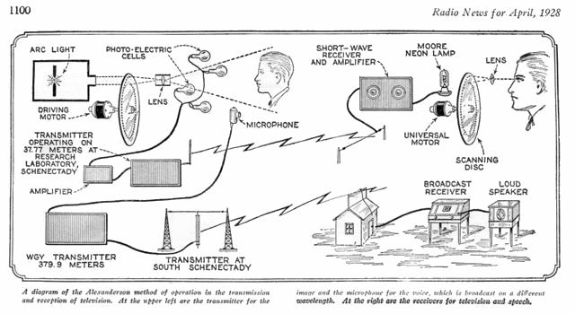
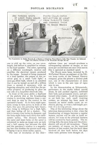
The two diagrams above show
how the signal was sent from the TV studio to the viewers, (about 1,000
mechanical TV's were sold for approx 25 pounds - the weekly wage was
about 1.5 pounds), so it's equal to about 4 month's wages! Originally
the sound was sent separately.
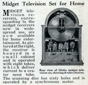
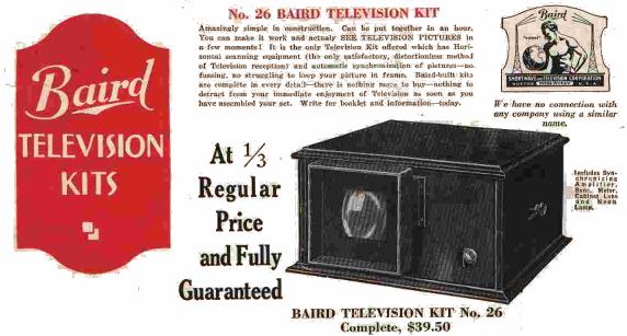
Here are two advertisements for kits:
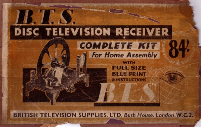
84 shillings is 4 pounds 4
shillings (called four guineas) or 2.8 weeks wages
Click HERE for larger image
Click HERE for larger image
Click HERE for larger image
Now you have an idea of the
concept, our project produces an image 8 pixels wide and 10 pixels high.
The program in the microcontroller produces a number of "cells" -
just like a film-strip, and they show different effects and patterns.
10 files are needed to produce a frame or "cell" and this is scanned a
number of times before the next frame is scanned. In the original
mechanical TV, pictures were broadcast live as no recording
apparatus had been invented.
When you look at the microcontroller program you will see a group of 10
values. These form a "cell" and by looking at the digits in each value,
a "1" indicates an illuminated spot on the display. In this way you can
"see" the picture that will be produced.
To create your own moving picture, simply add another group of 10 values
and put "1" in the positions where you want a pixel to show on the
display. The program takes these cells and displays them at a rate of 4
frames per second to produce movement.
THE CIRCUIT
Most of the operation of the circuit has already been covered.
However we will go over the basics once again.
A spinning sic with a number of holes is placed in front of an
illuminated screen. This screen is designed to diffuse the light given
off by a set of LEDs so the image is even all-over. As the disk
spins, the program in the microcontroller needs to know the exact
location of each hole so the LEDs can be turned on and off very quickly.
This is done by a small magnet stuck on the disk. When it
passes the inductor, it produces a signal that is firstly high then low.
(we connect the inductor so that the signal is firstly high then low) and this
100mV signal is passed to a transistor and amplified to get a 5v p-p
(peak-to-peak) signal. This signal is detected by the microcontroller
and used by the program to
produce a "starting point" for the first hole. By adjusting the position
of the inductor or the placement of the magnet, the first pixel can
be located at the top left side of the screen. Depending on the rpm of
the disk, the "on-time" will be adjusted to give a small dot on the
display.
The 8 bits of a file are then fed to the LEDs to turn them on and off to
produce a "scan row."
The program then has a delay before the next hole is in position and the
same is done for the second row.
After the 10th row we know where the first hole will be on the disk
but if the rpm of the motor is slightly more or slightly less than what
we expect, the picture will be offset to the left or right and will
"float" across the screen. We need to stop this. This is called
horizontal synchronisation. (vertical synchronisation is called rolling)
To keep the picture steady on the display we wait for the magnet to
pass the inductor. This starts the program at exactly the right time.
To produce the rpm required by the program, the motor is controlled by a
transistor. It receives pulses of energy to produce the required rpm, no
matter what supply voltage is available.
This is not extremely important as the rpm of the motor only has an
effect on the width of the image.
But getting the rpm to the value required by the program requires a
control on the current delivered to the motor. By providing a transistor
connected to the microcontroller, we can provide two things at the same
time.
1. the required rpm, and
2. maintain the rpm.
The first thing to do is work out the rpm you need.
For a full size screen you need over 20 frames per second. That's why
they chose 24 frames per second for movies. It is just above the
"flicker rate." Below 20 frames per second you can see flickering
on the screen.
This all has to do with the fact that you eye retains an image for a
short period of time after it has been received and if the next image
appear before the previous image has "faded away," the two images blend
together. All this is called PERSISTENCE OF VISION (POV).
To achieve 20 frames per second, the disk needs to spin at 20 x 60 =
1200prm. Each rotation has 10 lines and each line has 8 pixels. This
means each pixel has an ON time of: 1,000,000 / (20x80) = 62
microseconds.
ASSEMBLING THE
PROJECT
The kit of parts for this project
is complete but it involves both soldering and a lot of assembly. It is
not a "5-minute soldering job."
The most difficult thing in electronics is finding mechanical parts.
It may be linkage for a points motor on a model train layout or a
gearbox for a robot. Things like this are hard to find. And especially
items to connect a spinning disk to a motor or mounting brackets for a
motor. That's why you have to be good at mechanical assembly if you want
to build this project. The parts are provided but you must cut and shape
and glue them in position.
TESTING
We are dealing with
THE
PROGRAMMING A PIC
CHIP
This project is also designed to show
how to program a very small 8 pin PIC chip.
It is part of a range of projects using PIC chips.
Each project adds another area to the "design library" and this project
shows how to interface three devices. These are:
1. Input sensors,
2. Driving an oscillator and detecting its change in frequency, and
3. Driving a fairly heavy output load.
The chip used for this project is an 8-pin PIC12F629. Two
output lines are used for the motor, two input lines for detecting the sun and one
in/out line for the
position of the actuator, via an oscillator feeding an inductor -
leaving only one unused in/out line.
The project has been made as universal as possible, but if you want to change or improve the program, use our technique of
copy-and-paste where you change only a few instructions at a time.
To do this you will have to go to our:
Pick A
PIC Project page and select a programmer. From there you should look
through the projects and see how to start programming. The full list of
instructions for this chip are provided as well as lots of programming
notes.
This project offers areas for experimentation and you are welcome to
send in any improvements or additions you have created.
CONSTRUCTION
A full kit of components for Solar Tracker-1 is available from
Talking Electronics. It contains
a
pre-programmed chip and the parts shown in the parts list.
Some of the parts will not be needed for the 6v version but we have
included everything so you can create any version of the project.
Before starting assembly, you need to work out which parts of the
circuit you will be using and which links to add to by-pass the circuit
that is not required.
GOING FURTHER
This project is just one idea for controlling a motor via an optical
sensor. It has the advantage of being self-contained but can be
connected to the main solar panel via a regulator. Since the motor takes
between 2 - 4 amps, the regulator will have to be designed to deliver
this current and dissipate all the wasted energy. This is quite a
challenge. That's why we have designed the project to be cheap and simple.
It's the starting point to controlling a solar panel and getting the
best performance.
PARTS
LIST |
|
5 - 1 - 4 - 5mm red LEDs 4 - 5mm green LEDs (detect sun) 1 - 8 pin IC socket 1 - pre-programmed PIC12F629 IC "Solar" 2 - BC547 transistors 1 - 1 - 8 - BD679 Darlington transistors 1 - 1m very fine solder 1 - Solar Tracker-1 PCB Not in kit: heatsinks, nuts, bolts, threaded rod, wood, Power screwdriver, thick hook-up flex, |
Here are the files:
SkyWriter.asm
SkyWriter.hex
;Sky12F629.asm ;Sky writer with 5 LEDs for PIC12F629 13-5-2010 list ;oscillator calibration org 3ffh movwf OSCCAL end |
10/7/2010