|
MICRO BATTERY BOX |
- by Alan
just $2.00 for the box or $5.00 for all components
When an application or circuit is powered by batteries the device comes under a criteria of obligation. If a rechargeable power source is not being used then the batteries have to be replaced quite often in a high drain circuit.
| PARTS LIST 20cm - tinned copper wire 1 - SPDT slide switch 3 - button cells 1 - MICRO BATTERY PC BOARD |
Our range of mini FM bug are rated in the milliwatts for there power consumption this is a tiny value compared to other high frequency transmitters. This allows button cells to be used in there design.
The micro battery Kit came about because, there is already a surface- mount Bug, and the thought of having to solder individual button cells together to complete the miniature size of a surface mount kit is preposterous.
The fiddly linkages and the space wasted between cells connected to the main circuit eventually turns out to be quite a down side to a final surface-mounted device.
Due to the tiny size of the button cells they are a little more expensive than ordinary cells. And if they are to supply a greedy circuit or left to continuously power a circuit, then the comparison between the size of the bug and the life span of the batteries has to be considered.
When it comes down to having to replace the button cells most people would know that it is quite a task at hand. Having to desolder all of the linkages and then carefully, having to resolder the new batteries in to place as not to heat up the cells too much.
Button and lithium cells have a rubber seal between the terminal casing. If heat is applied for too long this will damage the seal and the battery will become leaky. This applies to any type of battery. A leaky battery has a short life span.
For these mini FM devices the two biggest components are; the batteries and the antenna.
But the Micro battery Box overcomes all of the replacement hassles. Being the cheapest way to provide you with the button cell battery holder
This gives you the capability, not only to use the cells in one circuit, but remove them and/ or the battery holder, to reuse them for another circuit.
So build the MBU and take advantage of powering all of your electronic circuits with this miniature power supply.
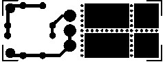
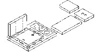
Step 1: On your workbench lay out the micro battery printed circuit board in the position shown in figure 1.
 |
|
 |
|
| Figure 1 |
Notice the area where many holes are drilled in straight lines to form a cross. This is where the board is scored to be cut, or easily broken into five pieces i.e the main circuit board and the four pieces (A, B, C and D) to form the side walls of the battery box.
Step 2: After the board has been split in the appropriate positions take note of the solder masked, land side of the four sides A, B, C and D.
 |
|
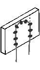
| Figure 2 |
This is where the looped linkages of tinned copper wire are to be soldered, helping to connect the sides to the main board. One of the pieces has two holes drilled vertically through it, shown as side ‘D’, with the help of the tinned copper wire this will be the negative terminal for connection to the battery.
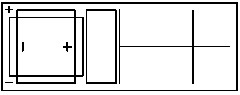
First line up each of the sides in turn, in their position on the main board and with a pen or texta, mark two vertical lines, straight up from the main board mounting holes . Do this on the silver side, which is the land side.
These markings will ultimately give you a reference when soldering the tinned
copper wire loops. As shown in the diagram, figure 3.
Repeat this step for all four of the sides; A, B ,C and D.
  |
|
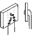
| Figure 3 |
Step 3: Cut 4 x 5cm lengths of of tinned copper wire and fold them into an equal sided, U or loop.
To prepare sides A, B and C, for mounting. Lay one of the sides on your work bench stuck to a blob of blu-tack, with the track side up to show your markings, made previously. Apply a small amount of solder at the bottom one of the markings closest to where the wire will be inserted down the main board holes. Line up a loop of wire to the markings and remelt the small dot of solder bonding the wire tot eh PCB, forming a temporary bond. This is so, there is no need to hold the wire while making the final solder bonds.
Wait for the joint to cool. Start again on the opposite size and then work your way round till the wire is fixed properly.
Repeat this for all three sides A, B and C, and leave them to cool.
Side ‘D’ is an exception to the rest, and is prepared a little different. Using the last loop of wire, bend it into a U shape and feed it through the two vertical holes in the PCB, opposite to the solder side. Flatten or flush the looped side of the tinned copper wire to the PCB, as this will protrude from the board to make contact with the negative terminal of the button cell (which is the center of the cell) this will prevent the outside rim and casing (that is the positive) from shorting out. Bend the tinned copper wire legs flush to the board (following Fig 3a) and solder in the same manner as sides A, B and C.
The loops of tinned copper wire are the joining wires or the legs, they are to be fed through and soldered to the main board to give the walls structural strength and join the battery contacts to the circuit.
 |
|
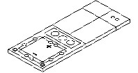
| Figure 4 |
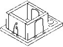
Step 4: Shown in Figure 1 are the sides, marked with there corresponding letters and there positions on the main board.
After the sides have cooled to room temperature from the soldering process for joining the tinned copper wire, to form there structural legs, the construction can start.
One at a time, position each side in the appropriate position and feed the wire down the corresponding holes. Keeping the wall flush to the main board, and at a 90º right angle. Turn the main board over and firmly bend the wire out-wards to hold the wall in place, so there is no need to hold it.
Solder the wire to the lands on the bottom of the main board and snip the excess leads off. Repeat this for all four sides as shown in figure 5.
 |
|
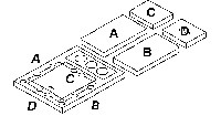
| Figure 5 |
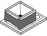
Finishing with the results shown in figure 6.
 |
|
| Figure 6 |
Step 5: If the sides are wiggled back and forth on there foundation too much the wire which is keeping them there will eventually snap. To prevent this, sticky tape is wrapped around the walls twice as shown; while the batteries are inserted, to give the holder the right size, and a firm grip on the cells to keep them in place, once the Micro Bat is completed.
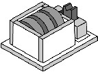
Step 6: Insert and solder the SPDT switch. To prevent the unit being left on when not in use, and powering a circuit which will eventually deaden the batteries. A marking on the ON side of the switch has to be made with White-out - liquid correction paint and red nail polish.
To do this face the Micro battery so that the switch is to your right and the batteries are to your imediate left.
Making the switch ‘ON’ if it is in the up position. If the unit is ON Turn it OFF. Apply a thin coat of white liquid correction paint to the top of the casing of the switch, wait a few minutes until it is properly dried and then add a few coats of red nail paint. This position of the switch is now the ON position.
Insert the batteries and the unit it finished and ready to use.
CONSTRUCTION NOTES
When connecting the Micro Battery Box to another Printed circuit Board, have
it in its OFF position. Make sure the Micro Battery Box is connected correctly to the circuit
with the positive terminal of the Micro Battery Box PCB going directly to
the positive rail of the PCB of the circuit it will be powering.
The Micro Battery Box has been designed so the two output terminals on the PCB are opposite to the usual format. This is so that the Micro Battery Box PCB can be wired in a back-to-back formation, with an insulating layer between the two track sides.