|
THE
MICRO BUG |
$14.50 incl all parts and PCB
plus $3.50 postage to anywhere in the world
to: P1 P2
![]()
 |
|
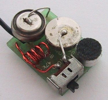
Another view of the underside of the Micro |
Even though the transistors are designed to withstand 10 seconds of soldering
in a wave-soldering machine, this does not mean you can take 10 seconds to
solder with a soldering iron.
The reason is the wave-solder bath is maintained at a precise temperature
and this is the exact temperature to complete the
soldering process without overheating the components.
Most soldering irons are above this temperature and this means the soldering
time must be reduced. For an iron 30°C above this temperature, the time must be
reduced to 3 seconds and for 50°C above, the time must be less than 1/2 second.
Most hobbyist irons come into the 1/2 second category and on top of this, only
one lead at a time must be soldered.
Once you know your soldering techniques are acceptable for surface-mount
components, and none are being damaged, you can you can work as fast as our
assembly section and fit the components about twice as fast as the through-hole
variety.
|
|
|
The Micro Bug
with two button cells soldered to the top of the board with a
miniature slide switch. |
|
|
|
The pinout of the SM transistor we supply in the kit |
THE SURFACE MOUNT TRANSISTOR
Now let's talk about the surface mount transistor.
When you open up your kit of parts you will get quite a shock.
The surface mount transistor is smaller than you think and in fact I think it
is too small for manual insertion. But that’s what you’ll have to face.
Certainly the designers of surface mount transistors had no intention of them
being inserted by hand as they are smaller than a surface mount resistor!
But any industrial prototypes have to be assembled by hand and this project
will be a good experience for later.
Above you see the outline of the surface mount transistor. The top of the
device is too small to fit the full type number and a silly code number has
been allocated as follows: BC 847, BC848 (NPN) is marked 1k, but most importantly it
is a three leaded package.
This is the same as BC 547. The tiny leads are so short that they just emerge
from the case and this means any heat from the soldering iron will travel to
the junction very quickly. You have only half a second to complete each solder
joint. Any delay will damage the transistor totally and it will fail to
amplify.
TESTING and GETTING THE CIRCUIT TO WORK
THE LED POWER METER
We are going to cover these two at the same time.
Testing the circuit and getting it to transmit on a particular frequency is
a learning experience. If the circuit does not work, this
is when you will start to learn REAL electronics.
I hope the circuit does not work and you have to fix it, but since our projects
have been tried and tested thousands of times, the chances of it not working
are very slim. The main fault will be overheating the components and damaging
them by trying to move them while soldering.
As I have said, this transmitter is an advancement on a number of projects we have already presented and it has been suggested that you build
some of the others to get you accustomed to the performance.
The first thing to do is see if the transmitter works (transmits).
Place it near an FM radio turned to medium volume and tune across the dial,
listening for a feedback squeal.
If a squeal is heard, the transmitter is operating on the FM band. If you don't
hear a squeal, don't worry as the circuit may be operating just
below the band and in this case you will not be able to pick it up.
To find out, remove the antenna lead and fit the
LED Power Meter.
It will only take 10 minutes or so to build this circuit and connect it to an
ordinary multimeter set to low volts range.
Once you have built it, you can go on to the next stage:
The LED power Meter is a simple RF detector using diodes to charge a capacitor.
The voltage developed across the capacitor is shown on a multimeter set to a
low voltage range.
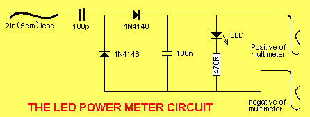
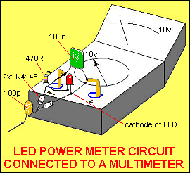
The circuit is soldered together without the need for a PC board, as can be seen in diagram below and paper clips are used for the positive and negative terminals of the multimeter.
The output of the Micro Bug is very low and you will only get a
very small indication on the meter and a very small glow from the LED.
The reading is not calibrated and does not represent milliwatts output. It is
only a visual indication.
|
LED Power Meter Parts List |
| 1 - 470R (yellow-purple-brown) 1 - 100p ceramic (marked 101) 1 - 0.1u (100n) ceramic (called monoblock) (104) 2 - 1N 4148 diodes 1 - 2in (5cm) hook-up wire 2 - paper clips No PC board required |
If the multimeter does not show a reading, the output stage is not working.
The two stages in this project are AC coupled (a capacitor separates them)
and they can be tested separately.
The first place to go to is the oscillator section. This is called and RF
oscillator as it is operating at approx 88MHz.
This is a difficult stage to test as it is operating at a very high frequency.
It is not possible to view the waveform on an ordinary 30MHz CR0 as the circuit
is operating at 88MHz and the CR0 will not display the waveform on the screen.
All it will show is a mass of lines
- if you are lucky. A 30MHz CR0 will also put such a load on the circuit that
it will cease to oscillate.
This means all you can do is take a few voltage measurements and check the
continuity of the trackwork.
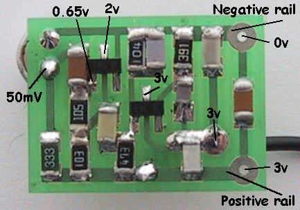
Firstly check the voltage on the collector of the oscillator transistor. It
should be 3v, indicating the coil is making contact through the board. Next
measure the voltage on the emitter. It should be about 2v. If it is 0v, the
transistor is not being turned on or the 390R is not making contact with the
board (the voltage will be about 2.5v to 3v, in this case). The base voltage
should be about 2.6v, and if it is much lower than this, the 47k resistor may
be the wrong value or the transistor is pulling the voltage down (due to the
emitter resistor being the wrong value and/or the base-emitter junction being a
short circuit).
 |
|
A guide to the voltages on the Micro Bug |
When you are probing around this stage, the load produced by the leads of the multimeter will often prevent the circuit from operating, so don't expect to get an output on the LED Power Meter when probing the board.
The main reason for this is the leads become an antenna and they absorb the signal.
The LED Power Meter can be connected all the time. It puts a very small load on the circuit and will not affect the performance.
The test-points on the PC
board
referenced to the circuit.
This will help enormously when fault-finding.
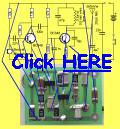
Click photo for large diagram.
Two problems remain. You cannot test the 47p unless you remove it and test it on a
Capacitance Meter. The same applies to the 10p. The cheapest and quickest thing
to do is replace the two components (the surface mount components are available
as spare parts).
The 1n is also very important and if it has been damaged during assembly (open
circuit), the oscillator will not function. This should also be replaced.
Lastly the 22n across the power rails must be in place to get a good output
from the oscillator. Try another 22n across it to see if the performance
alters. The only other things I can suggest are a shorted or damaged 100n input
capacitor and/or a damaged transistor.
Removing the transistor and testing it will be almost impossible as the heat
required to desolder the leads will destroy the component.
The only real choice is to replace the transistor and make sure you solder it
quickly.
Obviously you will have checked the freshness of the button cells, to make sure the
voltage is not too low, and the operation of the switch.
Just in case you are not aware, you cannot connect this project to a power
supply or to cells via long leads. The length of the leads will reduce the
"tightness of the circuit” and prevent the oscillator from functioning
properly.
This should get the oscillator functioning and you can now go to the antenna
point and measure the RF via the LED Power Meter.
You must get a reading (a slight reading) on the antenna-point before continuing.
SETTING THE FREQUENCY
The next step is to set the frequency of operation.
This could be below the FM band or above it as the commercial section between
88 and 108MHz is rapidly filling up.
When we first started producing transmitters the band was almost totally empty,
but as minority groups have begun to realize the power of voicing their view on
the airwaves, every local community group has its own radio station.
The separation between radio stations is now less than 100kHz and you cannot
get another transmission in between.
Just above or below the dial is sometimes the best solution and we have opted
for below the band when we sell made-up devices, as the range is better.
Simply by adding one more turn to the oscillator coil we can tune below the
band and adjust the turns to sit between courier companies and other users.
When thinking of transmitting above the band, you cannot operate between 120MHz
and 130MHz as this has been allocated to the emergency band and aircraft
traffic control.
With a reading on the LED power Meter you know the Micro Bug is transmitting
but you don't know the frequency of transmission.
If you want to operate on the 88 -108MHz band, turn on an FM radio and tune
across the band. When the radio is at the same frequency as the Micro Bug, it will
produce a loud squeal.
If you want to operate below the band you will have to detune the radio so that
it will go down to approx 86MHz.
This is done by moving the turns of the air-cored coil near the tuning gang so
that the stations move up the scale. This will create an empty spot at the
lower end of the band. You can also adjust the trimmers on the back of the
tuning capacitor to shift the stations up or down the dial.
In most cases you cannot shift the band very much as the stations begin to
"wrap around” the dial and the high stations appear at the lower end. Be
satisfied with a small shift. You should now tune the radio to the bottom of
the band if you have detuned the radio, or to the top of the band if you have
moved the stations down.
For a detuned Micro Bug, you should have 7 turns in the oscillator coil. Move the
turns of the coil so that you get a feedback whistle.
If you want to transmit above the commercial band, make sure you have 5 turns
on the coil.
One of the main problems with this part of the operation is finding the
frequency of transmission. The LED Power Meter will not give you this; it will
only let you know when the oscillator is operating.
You need a frequency meter or our FIELD STRENGTH METER MklI (to be described in
a future issue). It has a scale marked on the PC board, from 75MHz to 140MHz to
let you know the frequency of the signal you are picking up and a set of 3 LEDs
to indicate the relative strength of the signal.
If you get a reading on the LED Power Meter and an indication on the
Field Strength Meter Mkll to indicate the frequency is say 90MHz, but the radio
only produces a dead spot or quiet spot on the dial, it will indicate the audio
from the first stage is not coming through.
This means the fault will lie in the audio amplifier stage and/or electret
microphone. The first thing to do is take voltage tests and confirm your
readings against those given on the circuit diagram. The collector of the audio
transistor should be about half rail voltage (and the voltage on the microphone
can be as low as 50 millivolts) and the microphone will still be working
perfectly.
To test these stages more fully you need an audio oscillator or audio probe and
we have provided an audio injector probe on the
Combo-2 project.
Connect the earth clip of the Combo-2 project to the negative rail of the Micro
Bug
and inject a signal at the collector of the audio stage.
This will send a tone through the 100n coupling capacitor and produce a buzz
from the radio.
If this does not happen, the fault will lie in the 100n monoblock or maybe the
end of the capacitor that goes to the collector of the audio stage has a short
under the board, taking it to one of the rails and thus shorting out the
signal.
Once you get a signal at this point, move the probe to the base of the audio
transistor. The buzz from the radio should be louder.
If it is weaker, the audio transistor may not be amplifying correctly. It may
be damaged or open circuit.
Next, take the audio probe to the output of the microphone. If the output from
the radio is reduced, the 22n coupling capacitor may be open circuit or one of
the ends may be shorted to the negative rail.
If the output point of the electret microphone produces a loud buzz from the
radio, but the microphone does not produce any audio, the most likely cause is
a faulty microphone. Check around the microphone for shorts and solder bridges.
As a last resort, replace the microphone.
CONCLUSION
This completes the project. It is about as small as you can get and if you
have a fine-tipped soldering iron, it should be possible to get it working,
provided you follow our instructions carefully.
You will be very pleased when you turn it on as it will pick up the ticking of
a clock and anyone whispering nearby.
Surface-mount components are excellent for this type of project.
High-frequency projects like to be very compact as it improves the "Q-factor"
(the overall output of the oscillator stage) and surface-mount components
make the circuit very "tight."
Once you start working with surface-mount, you will realize it is the only way
to go.
We will be presenting more surface-mount projects in the future, keep looking
out for them.
![]()