POINT CONTROLLER using a SERVO
This is a project you will want to add to your layout. This project
controls a set of points via a SERVO. |
POINT CONTROLLER using a SERVO
There are many ways to position the servo to allow the lever to control
the points.
Placing the servo in its side will give better alignment.
|
These features are contained in our simple design and can be built in an evening. A kit of components is available from Talking Electronics as well as a pre-programmed microcontroller.
Size-comparison of the TORTOISE™
Slow Motion Switch Machine and BluePoint with Servo:
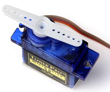
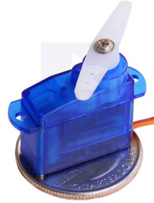
Comparison of prices for converting from manual to automatic: Using a SERVO is the cheapest way to automate a set of points and produces fully automatic operation for approx. $25.00 Turtle Point Controller project suits either a LINEAR ACTUATOR or SERVO. Both activate proportionally to the signal received via the signal line. Both have an IC that receives the signal and produces a pulse to the motor to turn it either clockwise or anticlockwise and the internal electronics compares the signal received from a pot or linear resistor to determine the angular or linear position of the arm. This project does not work with TORTOISE™ or Blue Point™ controllers. R/C (Radio Control) SERVO A SERVO is the cheapest way to control a set of points. This project operates the servo slowly to get the effect of a TORTOISE CONTROLLER with the advantage of placing the servo next to the track so you don't have to cut a hole in the layout or any other awkward installation. It is also much cheaper than any other controller. This is one of the servo's we tested. We call it MEDIUM SIZE. The LARGE servos are too big for this application.
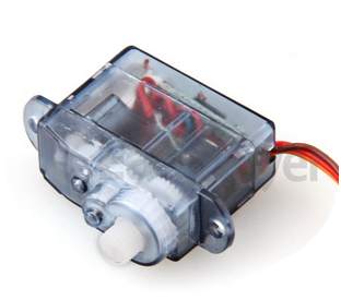
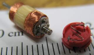
The all-plastic versions are much cheaper and have a very similar compound gearbox to reduce the output RPM and increase the torque.
A very SMALL SERVO uses a micro motor. A Micro Motor is
designed "INSIDE-OUT."
A Micro Motor operates just like a 3-pole motor. The winding is "skewed" (twisted) to produce smooth rotational torque.
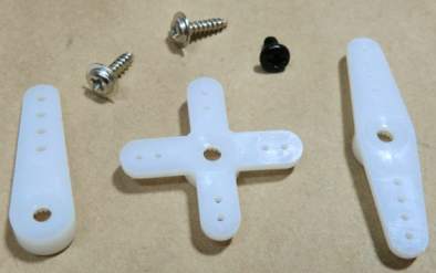
The servo in the kit is the MEDIUM SIZE and comes with a set of HORNS. These are commonly
called CRANKS or ARMS or LEVERS and connect to the output shaft with a splined connection (grooved) to prevent the arm slipping on the shaft.
Some come with a screw to hold the arm in place.
Single Horn or Arm Star or Cross Double Horn or Arm
SLOW-MOTION Using a "Star" or "Cross" to produce a linkage to operate the points with the servo near the track:
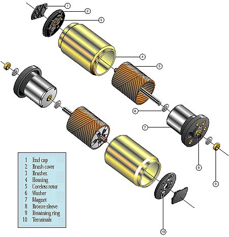
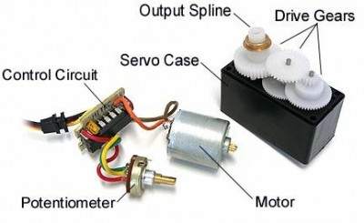
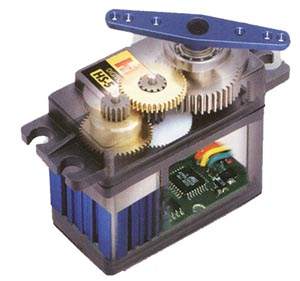
The project is designed to produce about 90 degrees of rotation for the servo. This produces enough "throw" to move the rails via a linkage. Here is a photo of the components in a servo from HOW AN R/C SERVO WORKS:
A Block Diagram of the electronics:
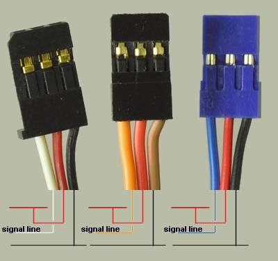
Most servos will rotate up to 180° and some will rotate to nearly 270°. Our project only needs about 45 degrees rotation to produce a THROW of about 10-12mm when a push-rod is connected to a hole near the axle. The track-points for HO gauge only need 8mm throw and this can be obtained very easily by connecting to a crank on the output of a servo. WIRING THE SERVO Servos come with different colours on the 3-pin connector:
THE CONTROL LINE The control line is called the "signal Line" and requires a waveform that is classified as a DIGITAL SIGNAL. This means it must rise to about 5v and down to about 0v to for the circuit inside the servo to respond. The time when the signal is high is called the MARK and the low time is called the SPACE. The width of the MARK determines the position of the output and it only takes a few cycles for the servo to respond and drive the motor to the angular location where the received signal matches the signal from the input potentiometer. The signal on the control line is called PULSE CODED MODULATION and the HIGH will vary from 0.5mS to 2.5mS. The LOW time needs to b e about 20mS. This means the coded signal arrives at about 50 cycles per second (50Hz).
5/5/2014 |

 .
.