SIGNAL
MODULE
Page 2
Go to P1
![]()
|
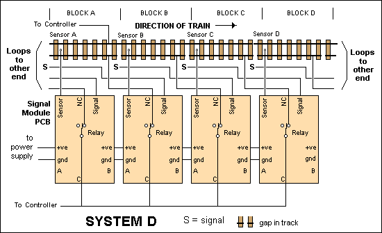
This is the simplest of the ways to wire the three aspect system but it does have a couple of problems. One is the signal at the beginning of the block containing the train will be displaying green. The other is the length of the wire required to go between the signals and the printed circuit boards. |
|
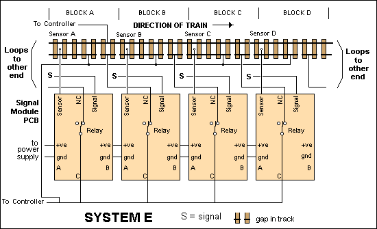
This diagram shows how to wire the modules for the more realistic of the two aspect systems. Each block is effectively a stand alone module, totally independent of the module to either side of it. Like all of the systems, there are no maximum number of modules that you can have in the loop. |
|
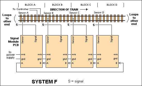
Of course if you don't want to block control, you can leave out the relays and the track wiring. This diagram shows the three aspect system without block control. For a two aspect system, leave out the wires linking the "A" pad on the board to the "B" pad on the next. |
|
Choosing the most suitable signalling system. |
|
This list of the advantages and disadvantages of the
various signalling systems will help you choose the most suitable for your
layout. |
|
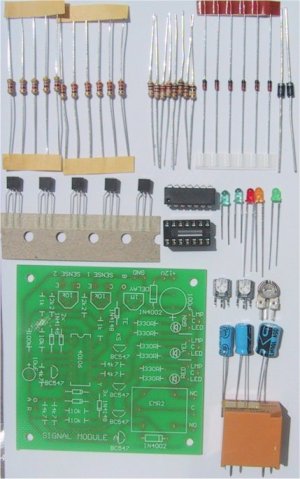
A close up of all the components contained in the Signal Module kit. |
|
PARTS LIST |
| 6 - 330R all 1/4 watt 2 - 1k 2 - 2k2 5 - 4k7 3 - 10k 1 - 100k 2 - 10k mini trim-pots 1 - 1M mini trim-pots 1 - 10uF 16v electro 1 - 100uF 25v electro 6 - 1N4148 diodes 2 - 1N4002 diodes 1 - 40106 Hex Schmitt Inverter 5 - BC547 transistors 2 - mel Darlington transistors 1 - Red 3mm LED 1 - Orange 3mm LED 1 - Green 3mm LED 1 - 14pin IC socket 1 - SIGNAL MODULE PCB |
|
EXTRAS |
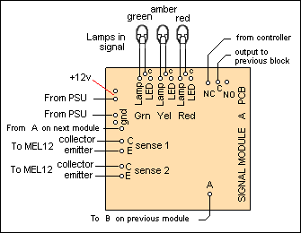
| This diagram shows the PCB wiring for the Signal Module. Some wires will not be required on the simpler systems. |
BUILDING THE MODULES
After deciding which system is most suitable for your
needs, you can commence building the modules. If you don't require the amber
lamp, its driver may be omitted, but I think it is a good idea to install it
anyway, just in case you decide to upgrade. The couple of components you would
save aren't worth much. If you don't require the block deadening function, the
relays can be left out. As these are worth a couple of dollars each, the
savings soon build up. Assembly is made very easy by the use of
clearly-identified PC boards. Start with the low components first, working your way up to the
tallest. Don't mount the MEL12 photo-transistors on the board. They should be
connected to short flying leads, so they can be pushed up through a hole
between the tracks. If the leads become too long, it may be necessary to use
shielded wire to stop induced noise from triggering the module. If noise
problems persist, try connecting 100n capacitors from the 0 volt rail of the
printed circuit board to pin 1and pin 13 of IC1.
The two 10k trim pots are for adjusting the sensitivity of
the sensors. Each one is mounted next to the input of the sensor it affects.
The third trimpot is for adjusting the length of the delay, to allow for
different block lengths.
Each driver has three outputs. One is for a grain of wheat
lamp, one is for a LED. The third is the LED on the PCB itself. These PCB
mounted LEDs make trouble-shooting much easier. If you are working on the
boards under the layout, it saves you having to crawl out every time you need
to look at a signal. If you wish, they could be mounted remotely on a mimic
panel near your throttle to let you know the condition of the signals around
your layout.
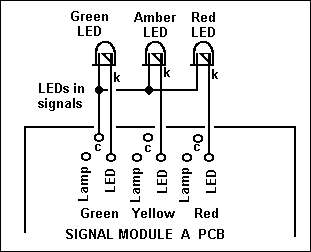
As I mentioned before, I think it is a good idea to use
LEDs instead of lamps for the signals themselves. If you do this, make sure
that you common the anodes of the LEDs (the long leads) and run the cathodes
back to the driver outputs. I managed to wire one of my signals as common
cathode, much to my dismay. To make it worse, it is the only signal
I can't remove to modify, as it is halfway down the underground loop on my N
gauge set. The other wiring error to avoid is connecting a signal made with
LEDs to the lamp output of the module. As there are no resistors in line with
these outputs, the LEDs would be destroyed instantly.
It is also possible to use tri-coloured LEDs for both two
and three aspect signals if you wish to model searchlight type signals. The
Searchlight Adapter to be presented in a future article is
ideal for adapting the three aspect output of the signal modules to the binary
signal required by the tri-coloured LEDs. Note that the tri-coloured LEDs to use
are the ones with three wires. A wire for the common cathode and one each for
the red and green LEDs. The tri-coloured LEDs
that have only two wires are a lot harder to drive, requiring a pulse train to
generate the yellow colour. They are not compatible with the system described.
One final note about the modules: when first switched on,
C1 will be discharged. This means that all signals will start on red, changing
to green as their delays time out. It will give you time to make sure your
points are all correctly set.
|
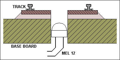
Mount the MEL 12 in the hole drilled between the rails. Its exact position will depend on the light source you are using. |
|
If you wish to use LEDs instead of lamps, wire them to the PCB like this. |
|
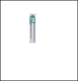
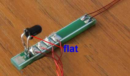
The MEL12 photo-darlington transistors looks exactly like a 3mm pale-green LED |
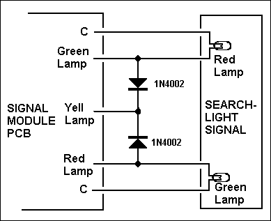
| If you wish to adapt a lamp-type searchlight signal so that it will work with the three aspect system. It can be easily done with two 1N4002 diodes. The "yellow" colour generated is not perfect, but is distinct enough to be recognised. Note that when you have done this, all three LED's on the PCB will light when amber is selected. |
|
The photos show both LED and lamp
type signals. The LED signal looks a lot neater and more to scale than the
signals using lamps. The LED's also light a lot more evenly, making the signals easier to see. |
|
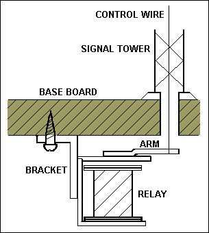
If you wish to experiment with semaphore signals, an old relay can be modified to control the signal. It must be a 12v relay, NOT a point motor. A stiff wire is soldered to the armature of the relay. The length of the wire will depend on how far the armature moves when it pulls in. The control wire or thread that runs up to the signal arm is connected to this wire. Arrange the signal arm so that the relay lifts it and gravity lowers it. Don't forget to put a 1N4002 diode across the coil of the relay. |
|
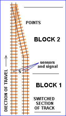
As mentioned in the text, the Signal Module can be used to stop trains colliding at a set of points or a diamond crossing. Due to the increased number of tracks that must be isolated, an extra relay may be required. The Remote Relay Unit from Electronics For Model Railways No.1 is ideal for this. It can be connected to the pad marked "R" on the Signal Module. The relay will close when the signal goes RED. |
ADDING INFRA RED DETECTORS
These IR detectors operate on a “break-beam”
principle and the receiver gets a beam all the time from the transmitting LED.
When a loco breaks the beam, the module detects this and changes the green
output to red.
You must connect the two IR sensors to the
inputs called C and E and the two IR Transmitting LEDs to the 12v and GND
with the two 470R resistors to the 12v pin and the other end of the
resistors to the anode of the TX IR LEDs (via the wiring) and the other pair
of wires to the GND pin.
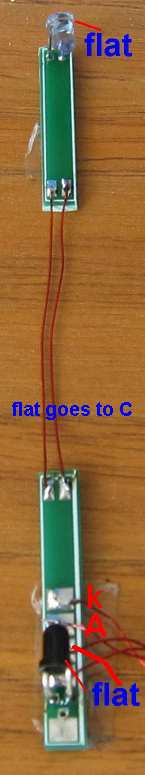
![]()
Sticky-tape the two sensor PC boards to your workbench and make sure the
LEDs face each other. Keep the two input sensors away from each other.
Turn the DELAY pot fully clockwise for the shortest delay and the two 10k
sense pots anticlockwise for the most sensitive positions.
You must use a 12v supply.
Connect everything and the red LED will come ON for 2 seconds and then the
green LED.
Do not have bright lighting on your work bench.
Move your hand into the beam of one sensor and the red LED will illuminate
for as long as you cut the beam and then the delay period AFTER you have
removed your hand.
Try the other sensor.
This is the way the IR LED works.
Both have a low voltage across them when detecting a beam from the IR
transmitter LEDs and the output of the first gates in the circuit produces
a HIGH into the next gate and the circuit also produces a HIGH at the point
too.
That means it is important for both IR receivers to be conducting to produce
this condition.
When one IR receiver does not receive a signal, the input to the gate goes
HIGH and the output of the first gate goes LOW and this goes to a diode-OR
gate and the circuit activates the red LED via another gate etc.