|
|

Original program by Keith Wilson
A memory game using a PIC microcontroller
The PC board has been designed for a PIC16F84A or PIC16F628
(it is supplied with a programmed PIC16F628 or PIC16F84A)
SIMON PC board is also used for experimenting
with PIC16F628: "Start
Here with F628"
| What
you can do with this project: 1. Build Simon using PIC16F84A micro 2. Build Simon using PIC16F628 micro 3. Investigate the F628 program 4. Study a 5v step-up regulator circuit 5. Use Simon PC board to experiment with a PIC16F628 |
|
P1 P2 P3 P4 P5 |
The PIC16F84A circuit - how
it works - construction PIC16F84A program PIC16F628 circuit Analysing the PIC16F628 program The PIC16F628 program |
|
This article describes a game we all know. It is SIMON. It uses 4 switches, 4
colored lights and a speaker to produce a sequence of tones and flashes that has to be repeated. After each correct
sequence, the computer adds another tone with its corresponding colored LED.
The main purpose for presenting this project is not to deliver a game but to show
programming routines.
This program is more complex than you would expect. Most of it is timing and
sequences but there are a number of features that have to be studied to to see
how they are carried out.
The notes (or tones) are produced by turning the mini-piezo on and
off at a definite rate and the length of each note is pre-determined by
loading a register with a value.
Each new sequence has to be generated and remembered and all these requirements
add up to a lot of programming.
Simon
Circuit
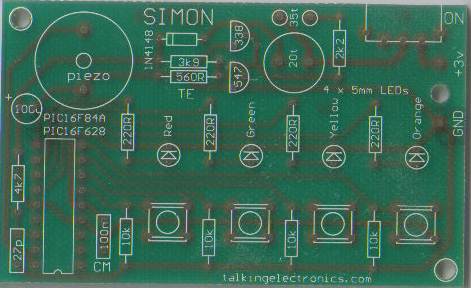
THE PC BOARD
The PC board has been designed to accept either a PIC16F84A or PIC16F628. With
the introduction of the'628 to the world market, it has taken over from the
PIC16F84A and we will be ceasing to design projects for the
'F84 and concentrating on the cheaper 'F628.
The two main improvements with this chip are the lower price and internal 4MHz
oscillator (as well as an internal 37kHz oscillator for low-power applications) - a
saving of 2 external components. It has three extra in/out lines and many extra
files.
The circuit consists of two parts - the power supply and the microcontroller.
We often put very little thought into the power supply section of a project and expect a battery to do the job perfectly.
It's not until you connect a battery and watch the voltage droop, that you start to think. That's what happened with this project.
To start at the beginning:
There are three ways to power this project:
1. A 6v supply with a diode,
2. A 9v battery with a regulator, and
3. A 3v battery with a step-up regulator.
We found the PIC16F628 chip very sensitive to over-voltage and some of the instructions failed to work when we supplied it with a voltage of 5.4v (we used a diode in the Tic Tac Toe project to drop the 6v supply to 5.4v and one instruction did not work when the supply voltage was 5v4). Some chips did not like this arrangement and so we will never use the diode voltage-drop idea again.
When we first designed the Simon project, we included a 5v regulator and connected a 9v transistor-battery.
After less than 1 hour of operation, the 9v was drooping and although the circuit is not critical to under-voltage, we could see the battery would not have a very long life.
So we changed the power supply to a step-up voltage regulator and used two cells to create a 3v supply. The rail-voltage on the chip remained at a constant 5v and the life of two AAA or AA cells was much longer than a 9v battery.
We then placed a "test load" of 100mA on the 5v rail and the voltage dropped only 30mV!
The step-up regulator proved extremely capable and will deliver 5v (actually 4.85v) with a single cell. This means the circuit will operate on 1.5v
The circuit was tested and operated on a single cell until the cell-voltage reached 0.65v The 5v rail was 2.3v The internal resistance of the cells was so high at this "end-stage" that it could only deliver 20mA! This was sufficient to keep the circuit operating!
HOW THE CIRCUIT WORKS
The heart of the step-up regulator section is the "fly-back" transformer - actually a transformer in fly-back mode.
The BC 338 is the driving transistor and is turned on via the 2k2 resistor. This produces magnetic flux in the primary winding that cuts the feedback winding and increases the voltage and current into the base to turn the transistor on MORE. This continues until the transistor is fully turned on.
At this point the magnetic flux in the primary winding is a maximum but it is not EXPANDING FLUX and it ceases to produce a voltage in the feedback winding. The transistor is turned off slightly and the reduced current through the primary allows the flux to start to collapse and produce a voltage in the feedback winding that is in the OPPOSITE DIRECTION. This turns the transistor off more and finally the transistor is fully turned off. The transformer considers the transistor is omitted for the circuit and the collapsing magnetic flux produces a high voltage in the primary winding that this is passed to the signal diode to charge the 100u.
The voltage across the 100u gradually increases and the two "detecting resistors" 3k9 and 560R produce a voltage-divider network with the base of the BC 547 at the "detection-point."
When the voltage on the base becomes 0.65v, the transistor starts to turn on and effectively puts a resistance between the base and 0v rail of the BC 338. This robs the BC 338 of "turn-on" current and thus it does not turn on as hard.
The output energy from the secondary winding is reduced and the voltage across the 100u does not rise any higher.
The "quiescent" or "idle" or "wasted' current has been kept to 5mA by making the base resistor 2k2 and the voltage-detection resistors 3k9 and 560R. When the micro turns on, the voltage on the 5v rail drops slightly and this turns off the feedback transistor slightly. The BC 338 is driven a little harder and the voltage on the 5v rail is maintained.
Although this "switched" power supply is a brilliant design, it puts a lot of noise on the power-rail.
The diagram below shows the 100mV spikes at 20kHz. Fortunately the microcontroller is a digital device and these spikes do not interfere with the operation of the program.
Spikes on the 5v rail
If an analogue circuit is added, the "spikes" would need to be
reduced.
See our Spinning Sign
project for one way to add an analogue input and prevent the noise on the
power-rail from upsetting the signal. One of the answers is to use a
transistor Schmitt Trigger and the Spinning Sign uses a transistor
Schmitt Trigger.
The rest of the circuit is the microcontroller chip. It has two ports, Port A
and Port B, and any pin can be configured as an input or
output. The 4 switches are inputs and the 4 LEDs are outputs, along with the
piezo diaphragm.
The micro is like a blank exercise book. It does nothing until it is
loaded with a program. Once the program is loaded, the internal
oscillator will read each instruction at a rate of 1 million lines
(instructions) per second.
If this is your first introduction to micro's, you should go to:
PIC LAB-1 or
Start Here with F628. They are designed to teach programming skills.
We cannot say anything more about the microcontroller as its operation is
governed by the program you have downloaded into its memory.
CONSTRUCTION
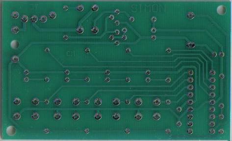
The PC board is clearly labelled with the position of each component:
The PC artwork
The only item you have to construct is the fly-back transformer.
Carefully remove the winding on the choke provided in the kit by cutting
the outer wire and unwinding the turns until only a few remain. Now put
20 turns (the feedback winding) onto the core and remove the enamel from the wire before winding
it around the pin and soldering. Make sure the wire is not tight as the
next winding is wound over this fine wire and you must be sure it will
not stretch and break. Measure the winding with a multimeter to make sure
it is making continuity.
The wire for the primary winding is included in the kit. Wind 35 turns
over the feedback winding and twist the two ends together to keep
it in position.
Solder the two pins of the transformer to the board. Remove the enamel
from the ends of the outer winding and solder them to the board.
This winding may be connected to the board around the wrong way, and will
be corrected after the project is fully assembled.
Fit all the other components, including the 18 pin IC socket, switch,
mini piezo diaphragm and battery snap (or leads from the 3v battery-box)
and insert the cells.
DO NOT FIT THE CHIP.
Turn the project on very briefly and monitor the 5v rail. If no voltage
is detected, the connection of the primary winding is around the wrong
way.
Reverse the connections and measure again.
The voltage should be very close to 5v.
Fit the chip and turn the project ON. It will play the commencement tune.
Here is the completed project on the Simon PC Board:
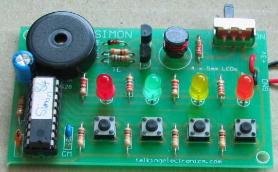
COMPLETE SIMON PROJECT
| |
|
P2 P3
12-1-2014