Stereo
VU Meter
Does your amplifier have a level indicator?
Have you always envied the fancy amps with LED level bar graphs?
Would you like to build your own STEREO LEVEL INDICATOR?
he complete kit can be purchased from Talking Electronics.
To place an order, click:
Stereo VU Meter kit

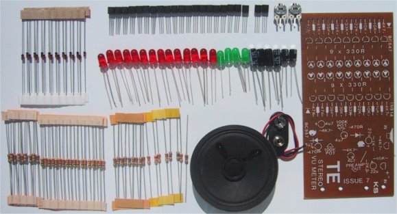
This is it. It's a STEREO LED LEVEL METER. It's the cheapest
and best bar graph display available and best of all, it uses readily available
components.
You only need a handful of LEDs, 22 transistors, some
resistors, diodes and a set of electros - it doesn't require any chips.
You may be wondering why we didn't choose the LM 3914 or
LM 3915 bar-graph LED driver chips. The reason is simple. We learnt our lesson
from our Mini Frequency Counter Book. In it we used a relatively
novel chip, the CD 4026. And after releasing 10,000 copies of the book,
with printed circuit boards attached, the chip became almost unobtainable in
Australia. This proved to us that many of the readers were making the Mini frequency Project.
Now, a chip such as the LM 3914 is
scarce at the best of times. Can you imagine what would happen if we used it in
a project? Ninety per cent of the readers would miss out. This means we must
confine our projects to readily available components and avoid rare items, no
matter how inviting they look.
We compared a LED level meter using the chip with our
unit and the difference was negligible. Both had the same quick response-time
and about the same readout values on the line of LED’s for the same input
signal. But the big difference is in the cost of construction. By using
transistors, you will save $4 over the cost of two chips. If you don't mind the
additional time required to fit the extra components, the $4 is a valuable
saving and by using discrete components, you can build it from parts you may
already have in stock.
|
|
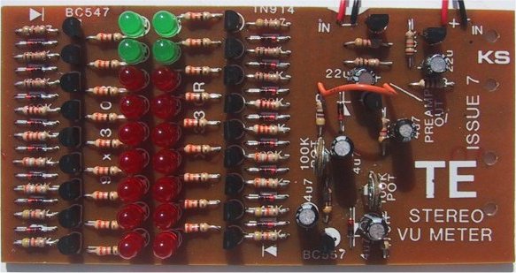
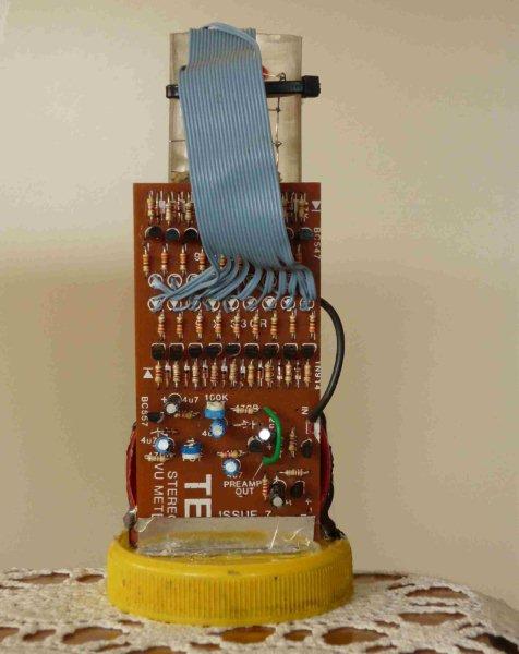
The Stereo VU Meter PC board with
the components fitted. Only the battery and speaker are external,
connected to flying leads. |
| A close up of the completed unit. The
overlay makes construction easy. Make sure the left-hand row of resistors
starts with 47k at the bottom and 4k7 at the top. I saw one unit with the
whole row reversed. It made very little difference to the performance of
the unit, but it was not quite as sensitive as the correct version. |
|
The BAR GRAPH
section of the Stereo VU Meter circuit. The "front end" section
is below: |
|
The BOOTSTRAP circuit connects to the LED bar graph via
A B C. Only one BOOTSTRAP circuit is provided on the board. It is capable of
driving both bar graphs in a mono mode. For a stereo readout, you will need to build another
bootstrap circuit. This will give a STEREO SOUND LEVEL INDICATOR.
|
|
The Circuit
The circuit basically consists of two identical channels feeding two rows of
LED’s. A highgain bootstrap front-end is also provided to allow the board to
be coupled to an inbuilt speaker/microphone which will give a mono readout of
the sounds being picked up.
A mini trim pot is provided to set the sensitivity. This
makes the project completely portable and it can be used as a SOUND LEVEL meter
in a disco or other noisy situation. To give a read-out in dB it would require
calibration. The simplest method of calibration would be to compare it with a
commercial unit and give each LED a value in dB.
If you build another bootstrap circuit, a portable
stereo sound detector can be made. It will be able to compare sound level in
different parts of a room or compare the relative outputs from 2 speakers.
As designed, each stereo section can be connected across the terminals of a
speaker and the unit mounted
in some prominent place for an eye-catching display.
Construction
Before you begin, lay the components on the work-bench in a position relative
to that on the PC board. Some of the parts have the same value, such as the
330R resistors. These should be positioned on the board with their tolerance
bands all around the same way. Separate the two BC557's from the other two
transistors and be sure you can identify the 22u electrolytic from the 4.7u.
The board looks deceptively simple because most of the
components are placed in rows. It will take at least one and half hours to
construct the project and the most important point throughout construction is
to create a neat appearance. This means aligning each component with the next
and keeping the heights all the same. Otherwise the neat appearance will be
destroyed.
|
|
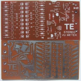
The Stereo VU Meter printed circuit board |
The suggested method of construction is to start with the
resistors and diodes. These should be inserted alternately as required by the
board so that you have maximum room when placing them in position.
Slow and sure wins the race. It is best to insert the
parts one at a time and push them firmly onto the board. Nothing looks worse
than a mass of floating components, some high, some bent this way, others bent
the other way. Once you push them onto the board, bend their wires outwards so
that the component is held in position. Turn the board over and solder the two
connections quickly. Check that the component has not shifted, then snip the
two wires. Continue down each row, adding one item at a time.
If you find you are closing over some of the holes
with solder when you are soldering, I suggest you only tack-solder the leads
and wait for the other component to be inserted, before finishing the joint.
Tack-soldering is very fast and requires almost no solder. This prevents the
solder flowing over other lands and filling up the holes.
You may have noticed that the two channels are a
mirror-image of one-another. This means the cathodes of the LED’s face outwards
and before inserting each LED you should look into their opaque body to make
sure they are being inserted correctly. In our prototype, the two top LEDs of
each channel are a different colour, mainly to add interest to the display. You
may choose to add another colour for the bottom two or three LEDs and produce
an even more exotic display.
The driver transistor for each channel and the bootstrap
circuit fits onto the right-hand end of the board. All the component values are
identified on the overlay and the two BC557's are shown as 'filled in', whereas
the BC547's are open 'D's'.
There are no jumpers on the board. However we have made
provision for connecting the bootstrap circuit to either one or both channels
via one or two links. These links are taken from the 'pre-amp OUT' point to
either the left hand channel or the right hand channel. |
|
PARTS LIST: |
18 - 330R
resistors
2 - 470R
1 - 1k
1 - 2k2
5 - 4k7
5 - 10k
2 - 22k
2 - 33k
4 - 39k
4 - 47k
4 - 4.7mfd 16v PC electrolytic
2 - 22mfd 16v PC
20 - BC 547 transistors
2 - BC 557 transistors
18 - 1N 914 or 1N 4148 diodes
14 - 5mm red LEDs
4 - 5mm green LEDs
2 - 100k mini trim pots
1 - 9v battery snap
1 - speaker 8 ohm
1 - VU METER PC board |
|
HOW THE CIRCUIT WORKS
The VU METER consists of 3 sections:
1. BOOTSTRAP CIRCUIT
2. BUFFER TRANSISTOR
3. STAIRCASE VOLTAGE DETECTOR
The BOOT-STRAP circuit is very successful at allowing a dynamic microphone in the form of a 2¼in speaker to
detect small sounds and have them amplified sufficiently to be fed into a
normal amplifier.
The BOOTSTRAP is rather unique in its operation. It uses
2 directly coupled NPN transistors wired in a similar mode to cascade to give
an enormous gain. In our prototype we measured this to be about 1,000 times!
In the quiescent condition, the transistors in the
bootstrap circuit are slightly turned on. This means they will accept a few
millivolts from the speaker and turn the circuit on harder or turn it off.
During quiet conditions 2 millivolts is developed across the speaker due its
resistance of 8 ohms.
Take the case where the speaker produces 2 millivolts
which is in phase with the quiescent voltage. This will turn the lower transistor
slightly off. The collector voltage will rise and in doing so, take the base
of the top transistor with it. The top transistor is partially an emitter-follower. Under normal circumstances, the collector
voltage of the top transistor would rise about .2v. This will make the emitter voltage of the
top transistor rise .2v (which is normal for an emitter follower).
Now the
top 22u electrolytic will transfer this .2v to the join of the 10k and 2k2
resistors and cause the top transistor and turn it ON further. This action feeds
around the transistor until the transistor can rise no more.
The top 22u was previously charged and some of its voltage is lost through the 2k2 resistor. This reduces the base
voltage and the transistor begins its downward excursion.
I have taken the extreme case. If the first transistor
does not turn on to quite the same extent, the emitter-follower will rise until
the loss from the top electrolytic prevents the transistor from rising any
more, and it begins to fall. The lower 22u prevents this swing from appearing
on the base of the lower transistor. It acts as a damper.
The output from the BOOTSTRAP can be as high as 2v p-p
and this is ample to drive the buffer stage. In fact the signal needs to be
attenuated by a pot so that the range can be set according to the amplitude of
the input signal.
The 470R resistor in series with the pot is only needed
when the VU Meter is connected directly across speaker lines.
The BC557 is not an emitter follower. Don't get confused.
It is wired as a normal common emitter stage for a PNP transistor. Thus it will
provide a high gain in this situation. The AC voltage appearing at the wiper of the 100k
trim pot will pass through the 4u7 electrolytic and become rectified by the
1N4148 diode. With no signal present, the voltage on the base will be 9v. As the
input signal increases, the voltage on the base will drop to 8.35v and this is
sufficient to turn the transistor ON fully.
The voltage on the collector will range between 0v and
8.5v. This voltage is stored in the lower 4u7 and applied to the
chain of 8 diodes. The 4u7 dictates the decay rate and gives the LEVEL METER
its rapid attack, slow decay characteristic and allows even brief peaks to be
detected. To reduce the decay time you can increase the electrolytic to 22u
and this will keep the LED’s illuminated for a longer period, similar to the
commercial units.
Between each diode is a high value resistor. As the
voltage rises to about .6v, the first transistor turns ON. At this stage the
voltage on the cathode of the first diode is 0v since the .6v has been dropped
across it.
The voltage needs to rise to about 1.2v before the
second transistor turns ON. This continues down the line with each transistor
turning ON at its allotted voltage level.
The set of 330R resistors limit the current through the
LEDs to a safe value and the base resistors serve as a voltage dropper so that
the base will not be forced to go higher than .6v. The number of transistors
which can be operated in this Staircase arrangement is limited by the battery
voltage available since each transistor and diode will take .6v from the
voltage.
TESTING
To test the stereo VU meter, connect the two links as shown on the board and
connect the dynamic microphone (speaker). Solder a battery snap to the board
and connect a 9v battery. This project is now a self-contained level meter and
will give a dual readout of the sound detected by the speaker. We are using a
small speaker as a microphone as we have had a great deal of success with its
sensitivity. No calibration is required. You only need to position the pick-up
(spkr) near a radio or stereo that is playing at normal listening level and
adjust the sensitivity controls. These are the two 100k mini trim pots in the
buffer stage. First you must set each one so that the top led is just
illuminated when a loud passage is being received. Then you need to trim the
two displays so they produce equal readouts for the same information.
FAULT FINDING
Since each channel is identical, you will be able to reference off one channel
to repair the other.
The ‘chain of transistors’ are all DC coupled, and you
can test their operation by using a 10k resistor connected to a set of jumper
leads. Connect one jumper to the positive of a battery and touch the other
onto the cathode of the lowest diode in the staircase. You cannot do any damage
to any component when probing around either channel and I suggest you take this
opportunity of seeing the effect of a turn-on voltage when applied to a set of
transistors.
When the 10k resistor is touching the cathodes, almost
all the LEDs should light up. By moving the resistor up the chain, the top LED
will light. This will show the channel to be functioning and you should test
the other channel for the same effect. If one LED fails to light, you may have
a base-emitter short in one of the transistors or the LED itself may be faulty.
If any LEDs above number 6 fail to light, one of the diodes may be open or you
may have a
dry joint.
If you have trouble getting one channel to function, you
can use the components from the other channel as test pieces. This is the great
advantage of having two identical channels. But by using parts from the good
channel, you could finish up with two bung channels. That's the risk you take.
The buffer transistor can now be tested by connecting the
10k to earth and touching the other end on to the base of the BC557 transistor.
This will illuminate one complete row of LEDs. The remainder of the circuit is
AC coupled via the 4u7 electrolytic.
Only the DC conditions of the bootstrap section can be
tested with simple equipment. Use a multimeter to detect voltages similar to
those given here: |
Both transistors will be turned on very slightly and
because it is a very high gain circuit, you cannot remove one transistor and
hope to get a smaller amplification.
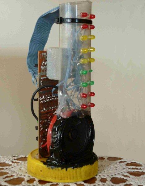
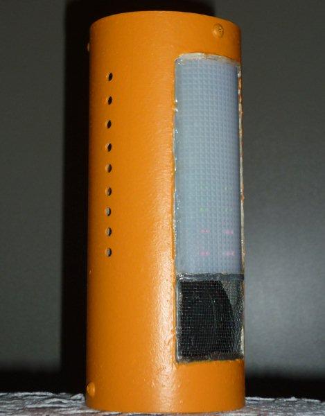
It will completely fail to work.Here is an application by Gerry
Holt:
He attends live music events in pubs and clubs. These "open mic" events enable
anyone with an act or instrument to put on a 15 minute performance. To curb the
enthusiasm of some 'artists' and reduce the pressure on the organisers, I saw
the need for a visible indication of the noise level in the room.
I built the Stereo VU Meter and mounted the LEDs separately and fitted a tube
over all the components. I painted the tube to make the whole project look
impressive. It worked so well, those running the event were ecstatic.
The tube is closed at the top and bottom with jam jar lids, the base lid having
sufficient clearance to house the battery (on a clip) and a small power switch.
The mesh allows the sound to reach the microphone (the speaker acts as a dynamic
microphone).
The complete kit can be purchased from Talking Electronics.
To place an order, click:
Stereo VU Meter kit
|
|