These projects have all been
created to solve a problem.
When you are developing a project, it has to be tested and TEST EQUIPMENT is often very
expensive.
We have solved the problem by designing our own.
Here is a selection of the projects we have designed . . . |
When you are building lots of circuits and using surface-mount LEDs,
there are many times when you have to test a LED to determine the
cathode and identify the colour.
You may also need to compare the brightness as some LEDs are TOO BRIGHT
and others are very weak.
I have even had the case where one end of a surface mount LED was not
soldered correctly and did not illuminate. I had to determine if the LED
or the joint was faulty.
That's why this little project was born.
The tester delivers only about 5mA to 7mA and this will help compare
high bright LEDs from poor-quality LEDs and also any LEDs that have been
damaged due to over-heating/soldering.
One of the big problems with surface mount LEDs is their susceptibility
to damage when being soldered. They are more-sensitive than transistors!
I have never damaged a transistor but some LEDs fail after the best
attempt at soldering.
That's because the light-emitting chip is only a millimeter from the
lead being soldered.
This tester will identify all these problems and it only costs a dollar.
Some of the old LED testers only tested loose LEDs with a current of
1mA, 10mA and 25mA, but this tester will test LEDs in-circuit as well as
surface mount LEDs.
This is the first handy piece of TEST EQUIPMENT for LEDs and there will come a
time when you wish YOU HAD IT.
The tester also has two more features.
It will test a shorted LED and continuity of tracks.
The LED on the tester will illuminate when the probes
touch each other and this proves the batteries are connected.
This feature can also be used as a continuity tester and will also
illuminate LEDs very faintly through the driver-resistors on the circuit
you are testing. So, it has many uses. Just add it to the range of TEST
EQUIPMENT designed by Talking Electronics and you will be ready for
designing and testing all sorts of projects.
Digital Multimeters (DMM's) will illuminate all types of LEDs (with positive
coming out the positive lead) but analogue meters using a single cell
will not illuminate any LEDs. But they will not illuminate
two LEDs in series and many of the projects we design have two LEDs
making a segment of a 7-segment display.
The earth lead is negative and the tip of the probe is positive.
That's why you need all types of test equipment.
THE CIRCUIT
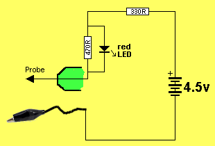
LED TESTER CIRCUIT
The circuit is very simple. It is just a 4.5v supply with a LED and
resistor in series. When the two probes touch they complete the circuit
and the "test LED" will illuminate. When the probes are across a LED,
only the LED being tested will illuminate. If the "test LED"
illuminates, the LED being tested is shorted.
When a LED on the PC board is illuminated, it will drop between 1.7v and
3.6v due to the characteristic voltage drop across the LED (according to
the colour). This leaves only 0.9v to 2.8v for the voltage across both
the 470R and 330R resistors, as they are in series. Since both resistors
are about the same value, the voltage across each resistor will be about
1.4v and this is not sufficient to illuminate the red LED. A simple but
clever way of turning off the red LED when a LED is being tested. It
only turns ON when a short-circuit is present.
This tester can also be used to test continuity.
It was used recently to determine the connections on a PC board from a
surface-mount 8-pin PIC chip to the 5 programming pins. The LED on the
tester illuminated when connected to the ends of a track. The adjacent
pins were also tested to see if any tracks were shorted to other tracks.
Just another use for this handy tester.
CONSTRUCTION
A kit of components is available from
Talking Electronics.
All the components are included in the
kit
and everything is identified on the board.
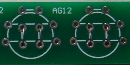
Fine tinned copper wire is fitted through the centre holes to make
contacts for the negative of each cell. These wires are carefully
soldered and the ends trimmed close to the underside of the board.
A cell is then placed over these wires and held in place with two wires
over each cell.
Here is a close-up of the tinned copper wire holding the cells in
place. The wires at the top of the cell use thick tinned
copper wire.
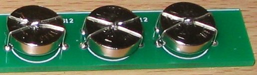
The cells are then held tight by drawing the two wires together
and joining them with a tiny dob of solder. They must not
move or they will lose contact.
Finally, each cell is held in position with a band of heatshrink:
Shrink the plastic with a cigarette lighter, but do it quickly so you
don't get the cells hot.
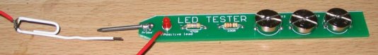
PARTS
LIST
$2.50
plus
$4.00 post
Order
a kit
|
1 - 330R resistor
1 - 470R resistor
1 - 3mm red LED
1 - 20mm nail for probe
1 - paper clip for earth lead
(or black alligator clip)
1 - 30cm black hook-up wire
3 - button cells - AG12
10cm tinned copper wire
30cm fine tinned copper wire
20cm very fine solder
3 - bands of heatshrink
1 - LED Tester MkII PCB |
|
There is a certain amount of skill required to design a circuit but a
lot of skill to simplify it.
There are lots of transistor tester circuits on the web and they all do
the one thing - identify a PNP or NPN transistor. Some provide the gain
and even the maximum operating voltage but in most cases we only want to
know the c, b, e pin-out and if the transistor is NPN or PNP.
That's what this tester does.
It lets you know the pin identification.
And, amazingly, it only uses a few components.
The secret is the transformer.
It's a flyback transformer that produces a high voltage when the
transistor switches off and this voltage is used to illuminate a single LED
for the PNP transistor and
2 LEDs for the NPN transistor. The two LEDs in series are used to
produce a voltage greater than 1.7v + 2.3v = 4v so the 4v can be used to
illuminate a white LED placed on the "Test LED" pins.
The project uses a single 1.5v cell and this voltage is below the 1.7v
needed to illuminate a red LED so no power switch is required.
There is only one trick to get the circuit working.
The phase of the transformer winding must be correct to get the circuit
to oscillate.
Both windings are 40 turns so it does not matter which
winding is used for the primary or which is used for the feedback. The feedback winding could
be a small as 10 turns but 20 turns or more is guaranteed to get the
circuit to work. But if the feedback
winding is not connected around the correct way, the circuit will not work.
There is no danger of excess current when the feedback winding is
greater than required, it just produces a very brightly illuminated LED.
You can learn a lot about the effect of one winding of a transformer on
another in this air-cored example by slowly bringing the two
windings together to see the circuit start to work.
When the flux density is very low, an air cored transformer is just as
good as iron or ferrite cored and when the current is turned off
very quickly in one of the coils, it produces a collapsing flux that cuts the
turns of all the coils and produces a high voltage in them of the opposite
polarity.
This is the voltage that illuminates the LED because the supply is only
1.5v and it is not capable of doing this. Thus we can prove it is the
transformer that increases the voltage. In fact the voltage is high enough to illuminates two LEDs in series.
If the LEDs are removed, the output peaks at 8v and operates at 700kHz.
The LEDs have a very fast response time and will detect the energy from
the 700,000 spikes per second.
The kit might cost only a few dollars but the experience gained by
experimenting with the two coils is invaluable. By bringing the coils
close to each other you will be able to see the point when the circuit
starts to operate.
This has never been covered before.
Most experiments are done with ferrites cores and you don't get to
understand the fact that air can transfer flux. This is especially
important with very high frequency circuits where the coil is always air
cored as ferrite does not have any advantage over air due to the losses
at high frequency.
The experiments with the coil have to be separate to constructing the
project as we will be concentrating on fitting the coils in the quickest
and easiest way.
This project will also detect the leads of a Darlington transistor
THE CIRCUIT
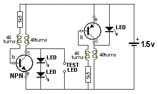
TRANSISTOR TESTER CIRCUIT
The circuit is very simple. It is just a 1.5v supply driving two
separate oscillator circuits.
You fit an NPN or PNP transistor into one of the circuits with the leads
around the correct way and the LED or LEDs will illuminate.
The 1k5 resistor limits the current into the base so the feedback
winding can produce a voltage that adds to the supply voltage and turns
the transistor ON harder to produce part of the cycle.
The operation of the circuit is quite complex because it involves the
action of a transformer and this is always
quite complex.
When current flows through a single turn of a coil, it produces magnetic
flux and this flux flows around the wire so that it all comes out the
centre of the turn. When more turns are added, the density of the flux
increases as each turn adds more flux.
The supply for this project is from a battery and it produces flux
called STATIONARY FLUX when a coil is connected to a voltage called a DC
supply.
But when it is initially connected to a DC supply, the flux
gradually builds up from zero to a maximum.
During this time the flux is called EXPANDING FLUX. This takes only a few
microseconds to occur.
When the coil is removed from the DC supply, the magnetic flux collapses
and it is called COLLAPSING FLUX.
Thus we can get 3 different types of flux from a DC supply.
When the flux collapses, it cuts all the turns of the coil and produces
a voltage in each of the turns that is opposite to the applied voltage.
In addition, this flux collapses very quickly and the voltage produced
is much higher than the applied voltage.
Finally, there is one more important fact you need to know about
magnetic flux.
When the flux is expanding or collapsing, it cuts the turns of the other
coil in the circuit and produces a voltage in the turns.
BUT when the flux is stationary, it does NOT produce any voltage in the
other coil. It is only EXPANDING or COLLAPSING flux that induces a
voltage in a second coil. The first coil is called the PRIMARY coil and
the other coil is called the SECONDARY COIL or FEEDBACK coil.
This means the PRIMARY coil produces a voltage in the FEEDBACK WINDING when the
PRIMARY is connected and when it is removed, but when it is fully connected
and producing STATIONARY FLUX, the FEEDBACK WINDING is not producing any
voltage.
This is the secret behind the operation of the transformer and you do
not know the magnitude of the voltage produced by either of the coils
until you build the project.
On top of this, you do not know how fast the circuit will oscillator
until it is built. These are all characteristics of the coil, battery
voltage, value of resistor, type of transistor, layout and many other
things. We are not going onto any of this as you can see the result and
measure the frequency, after you assemble everything.
The two coils of wire makes the circuit
a very complex arrangement that needs a high degree of understanding to
see how it works. We will try to simplify everything by getting you to
build the circuit and take measurements.
Two separate circuits are needed because an NPN transistor needs a
positive voltage on the base while an PNP transistor needs a voltage
that is less than the emitter.
Combining the two circuits would need a switch to change the positions
of the coils and a coil of wire is simpler and cheaper to add to the PC
board.
You can increase the brightness of the LED by placing a 100p to 4n7
across the 1k5 resistor. This changes the waveform from 8v to 7v but
increases the frequency to more than 1MHz and the width of the spike is
increased.
The capacitor effectively stops some of the spike being lost or being
driven into the 1k5 resistor and now turns ON the transistor more so a
greater current flows. This current produces a healthier waveform when
the coil collapses and delivers more energy to the LED.
The frequency increases because the transistor turns ON faster.
CONSTRUCTION
A kit of components is available from
Talking Electronics.
All the components are included in the
kit
and everything is identified on the board.
The only fiddly job is making the two transformers.
This is the last job. Make sure all the other components are fitted to
the board before making the coils.
Fit the NPN transistor to the board.
Wind 40 turns on a pen or shaft 12mm dia (0.5in) and make sure the shaft
is tapered so the coil can be easily removed.
If the shaft is parallel, add a match or the lead of a resistor to the
diameter and wind over this at the same time. Remove the wire and the
coil will become lose and easily removed.
Before you remove the coil, twist the two ends together three times and
cut the leads short.
Make 4 identical coils.
Place two coils on top of each other and keep them together by winding
the 0.25mm wire around them as shown in the photo above.
Do not solder the ends of this wire together as this will produce a
"shorted turn" and the transformer will not work.
Tin the 4 leads and fit two of the leads of one coil to the board.
Poke the other two leads down the holes in the board and the two LEDs
should illuminate because the project is COMPLETE.
If the LEDs do not illuminates, reverse the two leads.
When the LEDs illuminates, you can solder them in position.
Carry out the same procedure with the PNP transistor.
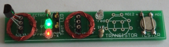
Here is a photo of an NPN transistor fitted to the tester and
illuminating the red and green LEDs. The LEDs are very bright because
HIGH BRIGHT LEDs are included in the kit.
With these two LEDs illuminated, you can test an individual LED,
including white LEDs, by fitting it to the 2-pin component header in the
middle of the board. The two LEDs will go out and the LED under test
will illuminate when it is fitted around the correct way.
The cell is held tight by soldering two wires across the top and
bottom when it is in position.
No on-off switch is needed because the battery voltage is lower than the
voltage needed to activate any of the LEDs. The unused
cell-position on the board is designed for a AG12 cell, just in case you
do not have one of the very small AG1 or AG4 cells. Only 1 cell is
needed.
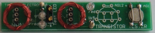
Transistor Tester
PARTS
LIST
$4.00 plus
$4.00 post
Order a kit
|
2 - 1k5 resistors
2 - 3mm red LED
1 - 3mm green LED
4m - 0.1mm enamelled wire for coils
1 - 20cm 0.25mm enamelled wire around coils
2 - 3-pin machine pin sockets
1 - 3-pin component header
1 - NPN transistor
1 - PNP transistor
1 - button cell - AG1 or AG4 or AG12
1 10cm 0.5mm tinned copper wire
20cm very fine solder
1 - Transistor Tester PCB |
|
|
LED TORCH
also
called
Joule Thief |
LED TORCH - JOULE
THIEF - INDUCTOR TESTER
Kit of components $3.00 plus $4.00 postage
An
equivalent IC (chip) has come on the market for 10 cents and it
is a better chip.
Here is the circuit for QX5252F:
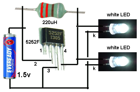
Using 220uH, the circuit takes 13mA an illuminates 2 white LEDs
very brightly.
Using 100uH the circuit takes 30mA and the LEDs are really the
same brightness.
Using 33uH the circuit takes 80mA and the LEDs are just about
the same brightness.
Obviously the 220uH creates the most efficient circuit.
Here
is the prototype:
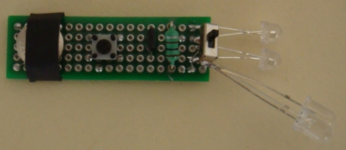
The kit
comes with a PCB, all parts: QX5252 Chip, tactile switch, 1.5v
button cell, tinned copper wire for cell and heatshrink for
cell-cover, 100uH inductor, very fine wire and 1M to make your
own 100uH, 2 machine pins and length of fine solder, but only 2
LEDs and not the change-over switch.
All for $7.00 posted.
Email
Colin Mitchell for
details on buying the kit.
The
prototype has been built on Matrix Board and shows the
change-over switch used to test different LEDs. You will get
the Printed Circuit Board in the kit that has been generated
from the layout. This is the easiest and simplest way to make a
PCB and avoid any mistakes.
The inductor has been fitted via machine pins and it can be
removed and different inductors fitted to see the results. A
machine pin is hollow and allows to poke the ends of a conductor
into the pin and it will make contact.
The current taken by the circuit changes according to the
inductance and this will enable you to compare inductors and
even find the value of an unknown inductor.
You need to use one, two or three known inductors and make a
table of the inductance and current taken by the circuit.
The current may or may not be linear but we measured inductors
from 33uH 1,000uH and recorded currents from 80mA to 2.5mA.
This enabled us to measure unmarked coils.
HOME-MADE
INDUCTOR
One more feature of this project is to wind your own inductor
and see if it is effective as the 100uH supplied in the kit.
The kit comes with fine wire and a 1M resistor.
Wind 250 turns on the resistor very carefully and as you come to
the end of the winding, you can criss-cross the wire over the
other turns to keep them in place.
Leave at least 4cm of wire at the beginning and end.
Now heat the wire very close to the body of the resistor with a
hot clean soldering iron that has been fully tinned. The wire
will get tinned very close to where it comes from the winding.
Now wind 5 turns around the wire coming from the resistor and
solder it in place. Break off the wire.
Do the same with the other end.
Fit your home-made inductor and the LED should be as bright as
the 100uH.
Measure the current across the switch. It should be about 32mA.
The voltage is being converted from 1.5v to 3.5v and each LED
will get slightly less than 6mA by the time you take the
efficiency of the circuit into account.
This
project will teach you 3 things:
The number of turns to create 100uH inductor, testing different
inductors, testing different LEDs and determining the value of
inductance by measuring the current.
|
LED Torch
PARTS LIST
$7.00 incl postage
Email
Colin Mitchell for
details
on buying the kit. |
|
The
LED Torch - Joule Thief
project comes with a PCB, all parts: QX5252 Chip,
tactile switch, 1.5v button cell, tinned copper wire
for cell and heatshrink for cell-cover, 100uH
inductor, very fine wire and 1M to make your own
100uH, 2 machine pins and length of fine solder, but
only 2 LEDs and not the change-over switch. All for
$7.00 posted.
Email
Colin Mitchell for
details on buying the kit. |
|
|
|
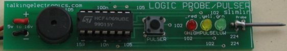
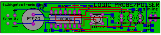
LOGIC PROBE
with
PULSER
(slimline)
Through-hole version
|
|
Kits
are available for this
project from Talking Electronics
$8.80 for through-hole version
|
We have 2 versions of this project. Version 1 uses one-eighth watt
through-hole resistors and version 2 uses surface-mount components.
You can decide which version you want to build and either one will be an
experience.
And the boards now have a mechanical buzzer that produces a much-louder
output.
These are all improvements and reflect the availability of components.
The project works the same as before. But the piezo diaphragms are
hard to get and very expensive.
A LOGIC PROBE is just one piece of equipment to help with
designing/testing and diagnosing a project.
And for $9.00 or $8.80 you can't pass it up.
It has two features above other Logic Probes. A pulser
to produce a waveform that can be injected into a circuit to produce
"clocking" or into audio circuits to determine the relative
amplification of a stage. And a mechanical buzzer to hear the presence of waveforms.
You won't be able to listen to very high frequency signals but many signals in a project
consist of scanning data and these can be detected as audio.
This project forms part of our overall aim to get you into designing
circuits using a microcontroller.
It teaches you how to use a Probe and Pulser and adds to your
understanding and analysis of circuits.
You don't need a Logic Probe until a project DOES NOT WORK.
That's when you reach for it.
And it is based on a very simple circuit.
It provides all the features you need and will detect HIGH/LOW voltages
on 3v to 15v circuits because the power for the Probe comes from the
leads clipped to the power rails of the circuit you are
testing.
This provides automatic adjustment for HIGH and LOW values to equate to
approx 50% of rail-voltage.
The project also has a Pulse LED to show when a single pulse is
detected. This is actually a "pulse extender" and is handy for
the time when you are waiting for a single pulse to arrive to activate a
circuit.
The piezo also monitors the input and you can hear the activity on the
line and compare one line with another.
The PULSER mode delivers a low frequency waveform and this will override
some of the waveforms in a circuit to slow-down the activation of a
circuit to see what is happening.
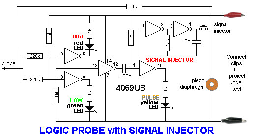
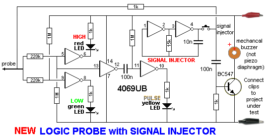
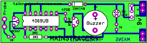
The latest PCB's use a mechanical buzzer (it contains a transistor and
metal diaphragm and
must be connected to the board around the correct way). It is
shown in the circuit above and the images below. It is driven in a very
clever
way by a transistor that is AC coupled to the input-line (from the
probe). It takes 1k to
discharge the 100n quickly so the transistor reacts to the signal.
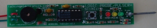
This is the Logic Probe using one-eighth watt resistors.
It is available as a kit for $8.80. (the cheapest Logic Probe kit on
the market)
This project has already been used to solve the following
problems:
No display on the Super Probe MkII project.
The clock pin was injected with the pulser and the Super Probe
MkII showed segments on the display at a very low clock-rate
to prove the microcontroller was working The problem was one of the 20Mhz crystal leads connected to 0v.
The 8x8 Module did not produce a display. The data and clock lines
were probed and it was found the data line was not connected.
The Logic Probe also helped with the input of the Point
Controller project to show when the photo transistor changed
from LOW to HIGH.
The Logic Probe helped to solve a problem with the Hourglass
Timer project. A track was missing !
You don't realise how many times you use a Logic Probe
until you keep a list of the incidents.
The illumination of the LEDs on the Logic Probe tell you a lot
of things. They show if a line is predominantly HIGH or LOW and
the piezo will let you hear the activity on a low-frequency
line. This has helped with the display section of the Stroop
and NIM projects.
It won't solve all your problems, but it will quickly find open
tracks (traces) and let you see the signal on each side of
components, such as LEDs, that are not connected to the 0v rail
(in a multiplexing or Charlieplexing arrangement).
|
Logic Probe
with
Pulser
Slimline
Parts List
for through-hole version
Cost:
au$8.80
plus postage
Kits
are available |
|
5
- 1k resistors
1 - 15k resistor
2 - 220k resistors
3 - 1M resistors
1 - 10n SM capacitor
2 - 100n SM capacitor
1 - 3mm red LED
1 - 3mm yellow LED
1 - 3mm green LED
1 - 14 pin IC socket
1 - CD4069UB
1 - BC547 transistor
1 - mechanical buzzer
1 - tactile switch
1 - 20mm x 1.2mm nail for
probe
20cm red and black hook-up flex
1 - red alligator clip
1 - black alligator clip
20cm very fine solder
1 - Logic Probe/Pulser PC board
- TH |
|
WHY TWO VERSIONS?
We mentioned to a sales outlet that we had a new
Logic Probe kit and said it used surface-mount components. He
wanted a through-hole version for beginners.
So we have two versions.
The PC board is very small so we had to use very small
resistors. The project goes together very easily and if you want
to advance to soldering surface-mount, this is the ideal time to
start.
You just need a pair of tweezers and a fine tipped soldering iron.
Once you try surface-mount you will be hooked. They are faster
to fit and make a much neater result.
USING THE LOGIC PROBE
Connect the red and black alligator clips to the project you are
testing.
This will automatically allow the Logic Probe to recognise a
HIGH and LOW and a change between these two values.
It is the voltage-level at which the Logic Probe changes from
HIGH to LOW or LOW to HIGH that is very important.
It must be very close to 50% of rail voltage.
Suppose you connect the Logic Probe to a 12v supply and work on
a 5v microcontroller project.
When the Probe detects a 5v signal, this will only be 5/12 = 40%
of the input voltage for the IC on the Probe and it will detect
this as a LOW !
That's why the Probe is always connected to the project being
tested.
Use the probe on lots of working projects to see how the LEDs
illuminate and the piezo responds to the signals.
This is the only way to find out what to expect.
You must compare your observations with a circuit diagram as
this will be your "library of resources" for future diagnosis.
When you are working on a faulty project, you will see the red
and orange LEDs brightly lit and the green LED very dull. This
indicates the line is mainly HIGH.
If the frequency of the pulses are between 50Hz and 10kHz, you
will hear them in the piezo.
USING THE PULSER
The project produces an output waveform of approx 330Hz when the
button is pressed.
This can be injected into a circuit to produce lots of different
effects.
The waveform is called a PULSER, CLOCK, INJECTOR, OSCILLATOR or
SIGNAL INJECTOR, depending on the type of circuit being
analysed (and how you want to call it).
It is especially handy when trouble-shooting audio circuits to
detect the gain through a stage. Audio stages are very difficult
to trouble-shoot, especially when three or more sections are DC
coupled. A signal injector will let you know
if a signal is getting through as some sections are current
amplifiers and the amplitude of the waveform does not increase.
CONSTRUCTION
All the parts fit on a slim-line PC board with
surface-mount components used to reduce the size and make to the
project appear very simple.
The latest PCB's use a mechanical buzzer as shown on the two
photo's using through-hole components. The piezo diaphragms
became unavailable.
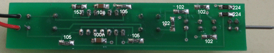
Two more SM parts are on the new PCB to drive the mechanical
buzzer.
(They are not shown in this version of the PC board)
All the values of the surface-mount components are identified on
the top (silk-screen) and the 10n is the same size as the 100n
so don't get them mixed-up.
|
Logic Probe
with
Pulser
Slimline
Parts List
surface-mount version
Cost:
au$9.00
plus postage
Kits
are available |
|
5
- 1k (102) SM
resistors
1 - 15k (153) SM
resistor
2 - 220k (224) SM resistors
3 - 1M (105) SM resistors
1 - 10n SM capacitor
2 - 100n SM capacitor
1 - 3mm red LED
1 - 3mm yellow LED
1 - 3mm green LED
1 - 14 pin IC socket
1 - CD4069UB
1 - BC547 transistor
1 - mechanical buzzer
1 - tactile switch
1 - 20mm x 1.2mm nail for
probe
20cm red and black hook-up flex
1 - red alligator clip
1 - black alligator clip
20cm very fine solder
1 - Logic Probe/Pulser PC board
- SM |
|
|
|
This is another piece of test
equipment from Talking Electronics.
It tests Infra-red LEDs. |
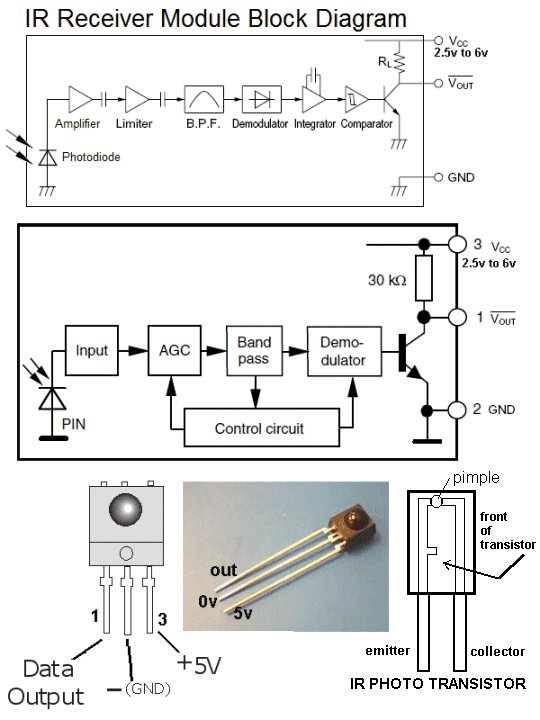
A piece of TEST EQUIPMENT is a useless piece of junk that
hangs around the workbench until it is absolutely needed.
And that's why this project was produced. It lets you know the
intensity of an IR LED and the quality of response when it is
transmitting 38kHz data. Without this project you are
completely frustrated. IR LEDs don't produce any visible
illumination and you need some sort of detector to prove it is
working.
Most cameras can detect Infra-red LEDs but this project also
detects LEDs that are pulsing at 48kHz.
This is the frequency used by infra-red remote controls for TV's
and stereos etc, but there are other very close frequencies and
this detector only responds to 48kHz.
And when you have a LED pulsing at 48kHz, you need to know the
frequency is accurate. The IR LED receiver (on the end of the PC
board) is designed to detect exactly a 48kHz modulation and this
allows you to prove the transmitting IR LED is working
correctly.
THE CIRCUIT:
HOW THE
CIRCUIT WORKS
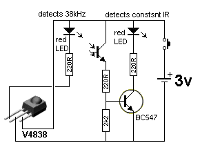
The circuit is very simple. It consists two different sections
(2 separate circuits). A transistor and IR detector detects
constant IR wavelengths and a 38kHz receiver detects 38kHz IR
signals.
We call the IR receiver a MODULE as it contains many
transistors, resistors and capacitors to produce a number of
amplifying stages that only allows a 48kHz frequency to pass.
This frequency is then compared to an internally generated 48kHz
signal and when the two are identical, the output goes LOW and
the LED connected to the output is illuminated.
The following is a block diagram of the stages. The BPF is a
Band Pass Filter and this stage only allows a very narrow range
of frequencies to emerge on the output of the block. This makes
it easier for the next stages to work and
produce a result.
But these's one little secret that no-one has mentioned.
The 48kHz signal from an IR transmitter must be turned ON and
OFF as a constant 48kHz will not keep the output active !!!!
V4838 Vs VS1838
There are a number of manufacturers of the 38kHz
receivers and some have no markings on them.
The Vishay V4838 is more expensive than the VS1838 but it does
not produce false triggering in sunlight. That's why we have
used it. You need to be careful when buying this component
because some are not marked.
CONSTRUCTION
All the components are fitted to the board and soldered
in the normal way except two items.
The 2k2 surface mount resistor is mounted under the board as shown
in the image above.
The IR receiving transistor is turned 90° after soldering, as
explained below.
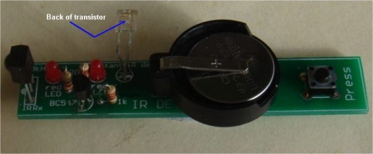
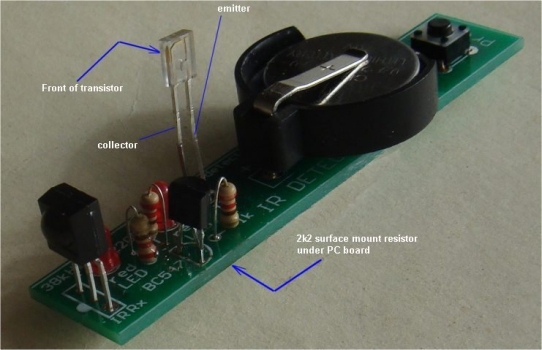
The IR receiver
transistor is bent 90 degrees by holding the two leads
with pliers
and twisting the moving the leads without them affecting
the component. Do not bend them without pliers or the
leads
will break off the plastic case.
The leads are very stiff.

The 2k2 surface-mount resistor is soldered to the lands near the
edge of the board
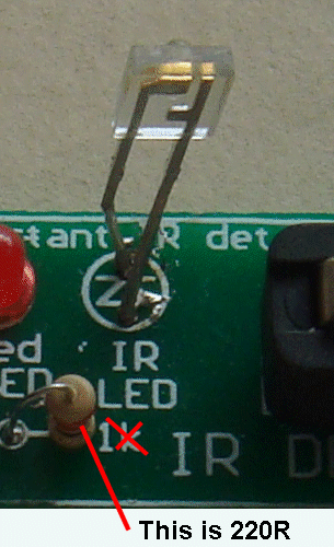
This is a close-up of the IR transistor
and the 220R on the PC board
The next batch of PCB's will have 2 improvements:
The holes for the IR transistor will be turned 90°
The 2k2 will be on top of the board.
|
|
3 -
220R all 0.25watt
1 - 2k2 surface mount (fitted under board)
1 - IR receiving transistor (any type number)
1 - 38kHz receiving module V4838
2 - 3mm red LEDs
1 - BC547 transistor
1 - push button (tactile switch)
1 - 3v lithium coin cell CR2032
1 - coin cell holder
1 - 20cm fine solder
1 - IR Detector
PCB |
|
|
|
Mains
Tracer
with long probe
Mains Tracer kit is available from
Talking Electronics for $10.00 plus $4.50 postage.
Click
HERE to buy kit. |
This project is one of the
projects that has been designed to support our article:
Become An
Electrician. It's a guide for those who want to become an
Electrician.
Having tried many of the Mains Detectors on the market, to find
they are not sensitive enough, this project was designed with a
number of improvements. The output is a buzzer, rather than a
LED to give a very good indication of the level of
electromagnetic radiation. The buzzer has an internal coil and
transistor, to produce a self-contained oscillator. It just
needs DC to activate. It is not a piezo diaphragm and has NO
piezo element inside the case. It is a metal diaphragm.
A MAINS TRACER is essential when trying to find a cable.
It works on cables in ceilings and walls. It will chirp when the
light-switch is turned-on and pick up the AC in a power cable.
When the probe is near electromagnetic radiation, the buzzer
reacts and this allows you to accurately detect the location of
the cable.
You can also detect the enormous amount of activity around a
computer (mainly the keyboard) and this may account for the
common occurrence of headaches.
You can also check for activity around the head of a bed to see
if electrical wiring in the wall is influencing your
night-sleep.
It will detect signals up to 30cm and is the most sensitive
detector of all those tested.
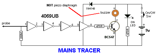
CONSTRUCTION
All the parts fit neatly on the PC board.
The IC fits into a socket with the cut-out shown on the overlay.
The placement of the transistor is also shown.
The buzzer must be connected with the positive on the buzzer going
to the hole with the "+" sign. The diode must be fitted with the
line on the body down the correct hole and the LED has a shorter
lead (cathode) down the hole marked with the arrow-head on the
symbol.
The most crucial item to connect is the battery snap. The "cup" on a
9v battery is the negative, but we are making a RECEIVING snap, and
the "cup" is the positive. You must look at the diagram to see how
this is connected.
MODIFICATION
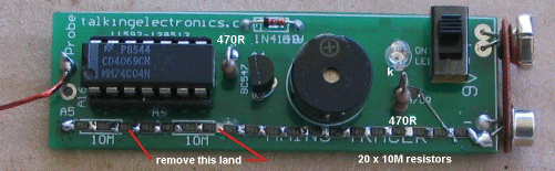
200Meg resistors are not very
common and it is necessary to make a value as close as possible to
this value by using a number of 10 Meg surface mount resistors.
Here is the way to place 17 x 10Meg surface mount resistors on
the board:
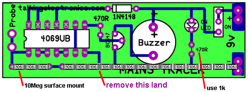
The land on the top of the board in
the position shown in the diagram above must be totally removed and
any traces of the plate-through hole material must also be removed
from the top surface so the surface-mount resistors do not contact
the 0v rail at this location.
Start at one end of the board and place a resistor. "Butt-joint" the
next resistor to it so that as many resistors as possible can be
placed along the board. We are aiming for 200Meg or as near as
possible.
The value of this resistor is very important as the input impedance
of the chip is very high and anything less than 100M will load the
input and reduce the sensitivity of the probe.
The 470R resistor for the LED can be increased to 1k as we are
supplying a high brightness LED in the kit.
MODIFICATION-2
VERY HIGH
SENSITIVITY
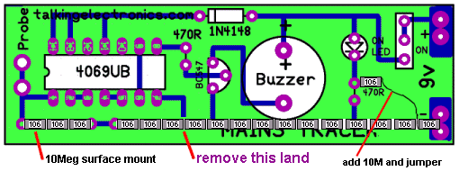
The completed project with the mods to make it
VERY SENSITIVE
The sensitivity of the project can be
increased by putting a "set" on the input voltage so the probe
responds to a smaller waveform.
This is done by adding a 10M resistor into the resistor on the front
end to provide about half-rail-voltage to the input.
This will mean the input only has to rise and fall a few volts to
change the state of the gate.
The "set" does not turn the buzzer on, but when the probe is placed
in an area of electromagnetic interference, only a small amplitude
signal is needed to alter the tone from the buzzer.
The probe will detect interference from the keyboard of a lap top at
20 cm and household wiring at more than 30cm.
You can check the radiation from the screen of your TV and from the
"Smart Meter."
MAINS TRACER -
CIRCUIT-2
The following circuit shows how to produce a high input
impedance using a transistor in emitter-follower mode.
It produces the same high impedance as the circuit above, without
having to use the string of 10M resistors.
The only problem is the circuit is not biased to create the
super-sensitivity of the circuit above.
You have a choice of building either circuit.
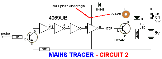
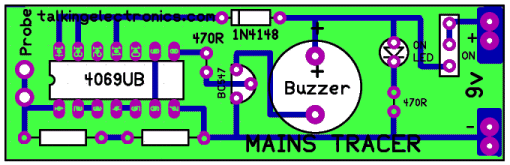
The Mains Tracer MkII PC board:
MAINS TRACER
MkII
Both PC boards are
included in the kit with all the components. You can decide which
board you wish to populate.
|
MAINS TRACER
PARTS LIST
$10.00 plus $4.50
postage.
Click HERE
to buy kit |
1 - 470R
1 - 1k for LED in place of 470R on PCB
1 - 1M
1 - 3M3
20 - 10M surface mount resistors
1 - 1N 4148 diode
1 - 3mm red LED
1 - battery snap
1 - CD 4069UB IC
1 - 14 pin IC socket
2 - BC 547 transistors
1 - buzzer
1 - mini slide switch
1 - 20cm fine solder
1 - 10cm tinned copper wire for battery snap
1 - 20cm 0.61 enamelled wire for probe
1 - Mains Tracer PC Board
MkI and MkII
(both boards supplied)
Not in kit: 1 - 9v battery
|
|
|
$15.50 plus
$6.50 post
Buy a kit

You won't need an audio probe like this very often but it is essential when
working with audio circuits.
Audio circuits are very difficult to diagnose, test and service.
That's because the signals are vey small and the voltages very low.
And the problem becomes even more frustrating when you have 3, 4 or 5 stages
that are all DC coupled.
You don't know where to start.
The voltages are only correct when everything is working.
If a transistor fails, everything changes.
Audio signals are also difficult to trace through wiring and plugs and
sockets.
It could be a short-circuit or an open track or a plug not making contact.
All these things have happened and over the years, this Mini Audio Amplifier
has solved over a dozen problems and made testing very easy.
It is just one more piece of test equipment designed by Talking Electronics
to help you design, service and test projects.
It has also been used to help trace a fault in an FM bug. The voltages on
the front end are too small to read on a multimeter and those that were
taken, appeared to be correct.
But the bug produced no audio.
One of the faults, as I remember, was a surface mount capacitor. One end was
not soldered properly and did not make contact with the PC board. The other
fault was a cracked 22n surface mount capacitor. it would have been
impossible to find these faults without an audio detector or a CRO.
I also remember a fault on a bug where the track was broken.
But one of the most frustrating jobs I had to work on was a new PCB and a 4
transistor push-pull DC coupled amplifier.
These are impossible to work n of the circuit is incorrect or a transistor
is faulty.
I cannot remember the exact fault, but the audio probe solved the problem.
It may have been a transistor around the wrong way or a track going to the
wrong component.
Even with the tester, it took a while. There is almost no other way to
locate these types of faults.
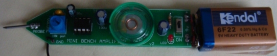
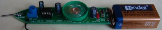
MINI BENCH AMPLIFIER
Some of the projects you can test with the Mini Bench Amplifier are tone circuits while others are audio
circuits. Tone circuits and audio stages are surprisingly difficult to
test unless you have an audio probe or a CRO.
A CRO is an ideal piece of equipment but if your budget does not
extend this far, the next best thing is an audio probe.
MINI BENCH AMPLIFIER
CIRCUIT
There are lots of things that can go wrong with an audio stage. It can
produce distortion or a “hollow” sound, go weak or simply fail
altogether.
Likewise tone circuits can present a number of faults and it is very
handy to be able to “hear” what is going wrong.
It is not sufficient to measure the DC voltages on these stages. This
only gives a partial picture of the conditions and does not tell you the
quality of the audio being processed. To determine this you need a piece
of test equipment that will let you see or hear what is being processed.
Firstly we will cover the benefits and problems of using a CRO.
The main problem with seeing the waveform on a CRO is you have to
interpret what you see and work out if distortion is present and where it
is coming from. Believe me, this is harder to do than you think.
Let me give some examples from a TV service-man friend. He has
serviced some 35,000 TV sets over a period of 15 years and in that time
he has used a CRO on a number of occasions to try and find faults in
audio stages.
One particularly troublesome audio fault occurred in an old black and
white TV set, so he got out the CRO to try and solve the problem.
The audio was weak and distorted but since the signals around IF
transformers are very small even when the circuit is functioning
correctly, he could not locate the fault.
Audio waveforms are seldom shown on circuit diagrams and it is
difficult to know if the signal you are viewing on a CRO is faulty or
correct.
To fix the set he had to resort to the old tried-and-proven method of
replacing components one-by-one. The fault turned out to be a 100p styro
in one of the sound-IF cans. It had gone open-circuit and reduced the
audio. But the CRO didn't pick it up.
There were other occasions when he tried to use the CRO but the result
was the same. It didn't really help.
If you are a highly qualified audio technician and know the waveforms
you should be getting at each location, it will be a completely different
situation to trying to find an unknown fault in an audio stage. Sometimes
an audio waveform is very messy when viewed on a CRO and yet the audio is
quite clean. Other times the waveform appears to be quite good and yet
the signal is distorted.
If the CRO was the answer to these problems, I would have no
hesitation in suggesting you buy one, but it can sometimes create more
problems than it solves.
To produce an audio waveform suitable for viewing on a CRO, you have
to inject the stage with a steady waveform such as from a function
generator or sine-wave oscillator. You cannot simply supply it with a
signal from a radio station as the signal will be varying in amplitude
and changing in frequency. The CRO will not be able to “lock in” and
produce a stationary waveform.
You cannot work on a display that is constantly moving. This type of
display is only suitable for amusement at a science exhibition. The
screen must be perfectly stationary so you can view it and take
measurements.
You need to measure the output and compare it to the input.
This is where a dual trace CRO comes in handy. On this type of CRO you
will be able to display both the input and output at the same time and by
super-imposing them on top of each other. You will then be able to see the
differences.
Alternatively you can display one waveform above the other and pick
out the differences.
If you only have a single trace CRO, you will need to switch from the
input to output as quickly as possible so the differences can be
detected.
Even when you see a difference you will have to work out if it
represents a fault.
An audio stage does not always produce distortion due to clipping or
over-drive, it sometimes sounds `hollow' or `tinny' due to the coupling
capacitors being too small or dried out. These types of faults will not
be picked up on a CRO and I suggest you save your money at this stage and
buy the Mini Bench Amplifier.
It will enable you fix audio faults very easily and save you a lot of
frustration.
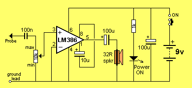
THE LM 386
The LM 386 is a high power op-amp. It is used to drive a speaker.
The inverting input has been connected to the negative rail and the
non-inverting input has been connected to a capacitor. Resistors inside
the chip bias this input so that it only requires about 7mV before the
chip turns on. This voltage is called the off-set voltage.
When a signal is applied to the “+” input, the chip amplifies the
waveform and the result appears on pin 5. The gain of the chip depends on
the impedance of the path between pins 1 and 8. We have placed a 10u
between these pins to get a gain of 200.
The chip will give a constant hum to show the circuit is working and remind
you that the project is ON.
FIXING AUDIO STAGES
As we said, there can be lots of problems with audio stages. Sometimes
they develop over a period of time, or they can be present from the
moment the amplifier is assembled. You can also get intermittent faults,
drop outs, squealing, motor-boating, distortion or simply lack of gain.
The amplifier presented in this article is used as an audio probe by
listening to the loudness and quality of the audio going into the stage
under test and comparing it to the audio emerging from the output of the
stage.
You do this by putting the earpiece near your ear and
listening carefully - that's why the probe has two long leads.
We could write a book on fixing audio stages but to reduce it to one
page, here is the approach:
The simplest situation is a single transistor amplifier with a
distorted output.
The first thing to do is replace the transistor. Even though
transistors are very reliable devices, you may have overheated it and
this will cause the device to have a different gain and thus the voltages
on the stage will not allow the signal to be processed correctly (you can
put it back later if it is not the cause of the problem).
The next thing is measure the voltage on the collector. Ideally it
should be half-rail. This allows the transistor to turn on and off THE
MAXIMUM AMOUNT and thus give the stage the maximum gain.
To carry out any more investigation on the stage you will need a copy
of the circuit diagram. This will let you know how the transistor is
biased and may give details of the voltages at the various locations.
Next look at the electrolytics. These can be inter-stage devices,
decoupling or emitter bypass capacitors. They can dry-out and lose their
capacitance or go open (very rarely) or go short-circuit (very rare).
Tantalums can also go short-circuit as they are susceptible to high
voltage spikes that puncture their ceramic substrate.
If the transistor has an emitter by-pass capacitor in the form of an
electrolytic across the emitter resistor, the stage gain will be severely
reduced if the capacitor (electrolytic) has lost its capacitance (dried
out).
A faulty inter-stage capacitor (one that connects the output of one
stage to the input of the next) can be checked by placing the probe one
side of the capacitor, then the other. If the audio level drops
considerably, the capacitor is not passing the signal and may be faulty.
If you have replaced the transistor with another type, the voltage on
the collector may be different to that specified.
If it is lower, the transistor has a higher gain and the base-bias
resistor must be increased. If it is higher than expected, the base-bias
resistor must be decreased.
This only applies to simple self-biasing stages, where the base-bias
resistor sets the collector voltage for the stage.
Resistors rarely give trouble except if they are of an old style or in
a position where they get hot.
If hum is present on the audio, the fault will lie in the filtering of
the power supply. If a squeal similar to a feed-back squeal, (as heard
when a microphone is too near the speaker of an amplifier), the fault can
be in the decoupling capacitor. This is generally a small value
electrolytic (10u to 100u) near the stage it is protecting and will be
associated with a low value resistor on the power rail. The electrolytic is
connected across the power rails.
This electrolytic can also produce a fault similar to the putt-putt-putt
of a motor boat exhaust system, bubbling through water.
The Mini Bench Amp has a volume control in the form of a gain control,
to vary the output volume from the earpiece. The approximate gain is
marked around the control.
An additional probe can be connected to the board via a small socket
and this will allow the Mini Amplifier to be brought up to your ear so
you can listen to the audio.
CONSTRUCTION
Everything fits on the PC board supplied in the kit.
The IC socket is fitted so that the notch at one end corresponds to
pin 1 and covers the cut-out on the overlay. This helps when fitting the
IC at the end of assembly.
The cathode of the LED is identified by a flat side on the body of the
LED and this is the line on the symbol on the overlay.
|
Mini Bench Amp
Parts list
$15.50 plus
$6.50 post
Buy a kit
|
1 - 1k
1 - 10k mini pot with shaft
1 - 100n monoblock capacitor
1 - 10u 16v PC mount electrolytic
2 - 100u 16v PC mount electrolytic
1 - LM 386 N1 400mW amp chip
1 - 8 pin IC socket
1 - 32R mini speaker
1 - 3mm red LED
1 - battery snap
1 - 9v battery
1 - SPDT slide-switch
1 - long nail for probe
1 - black alligator clip
1 - 25cm black hook-up wire
1 - 10cm 0.5mm tinned copper wire
1 - MINI BENCH AMP PC Board
Kits for
MINI BENCH AMP can be obtained from Talking Electronics:
http://www.talkingelectronics.com
|
The three electrolytics have a line down one side indicating the
negative lead. The board has the positive lead marked with a small plus
("+") sign.
The only other item needing a little care is the battery snap. It is
removed from the plastic covering and the two lengths of wire snipped
off, the two eyelets are tightened by hammering with a centre-punch. It
is then fitted as shown in the following three diagrams:
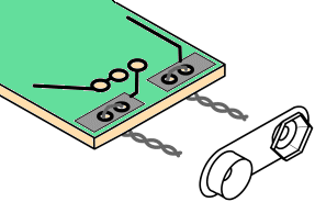 |
Fig1a.
The bottom of the board is shown. The wire is looped from the
bottom and twisted. Note the polarity of the battery snap.
|
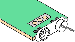 |
Fig1b.
The battery snap is pushed up to the board and the twisted wires
are cut short.
|
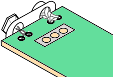 |
Fig1c.
Both the top and bottom of the board are soldered to the battery
snap to keep it firmly in position.
|
The 9v battery is clipped directly to the board via the battery snap.
The optional probe uses red hookup wire and an alligator clip otherwise
use a paper-clip or nail soldered to the end of the board.
The paper clip must not be cut with side-cutters as it is made from
hardened steel and will damage the cutters. The only way to
cut the clip is to file a niche in the wire and bend it back and forth
until it fractures. This probe is then soldered directly to the board
with some wire loops that add strength. It is called the active lead as it
goes to the ‘active’ input of the chip.
The ground lead uses the black hook-up wire and has an alligator clip
soldered to it.
All the other components are fitted close to the board and leads
are snipped close to the board after soldering. Fit the IC and 9v
battery and the project is complete.
IF IT DOESN'T WORK
Switch the Mini Bench Amp on and turn the gain control to maximum. Touch
the active probe with your finger. You should hear a slight buzz from the
speaker. This is a quick test to show the project is working. If nothing
is detected, you should follow these steps:
If the power LED doesn't come on, the most probable cause is a flat
battery or the battery terminals not making contact.
Also check the placement of the LED as it may be around the wrong way.
Next check the current taken by the circuit, across the switch (with
the switch in the OFF position). It should be about 10mA.
If no sound comes from the speaker, measure its resistance with a
multimeter. It should produce a slight `click' when you do this and
measure about 32 ohms.
Check that pin 1 of the IC is near the cut-out on the overlay and see
that all the pins of the chip are entering the socket. Sometimes a pin
bends over and does not make contact. Also make sure all the pins of the
socket are soldered to the board. This applies to all the other
components. Finally, make sure the positive of the battery goes to the
positive rail on the board and the negative goes to the negative rail.
There is little else that can go wrong and the project should be
working by now.
USING THE MINI BENCH AMP
All you have to do is connect the ground lead to the project you are
testing, switch the Mini Bench Amp on and also the project you are testing.
Use the probe or the active lead to probe various points on the
project under test and listen for the audio. The gain control on the
Mini Bench Amp is very similar to a volume control and will allow you to hear
the audio without too much over-drive.
Most amplifying stages have a gain of about 50 - 70. Some will have a
gain of about 100 but this is about as high as you will get.
It is impossible to describe how to determine if a stage has high or
low gain, merely by listening to it. The only way to work out a gain
factor is to use a CRO.
One clever way to fault-find a project is to get another identical
unit and compare one with the other.
To do this you need to set both beside each other and join the
ground lines together. Turn them both ON and you can then probe each
stage and compare one with the other.
If you have had the frustration of trying to diagnose an audio stage, you
will find this project absolutely essential.
|
|
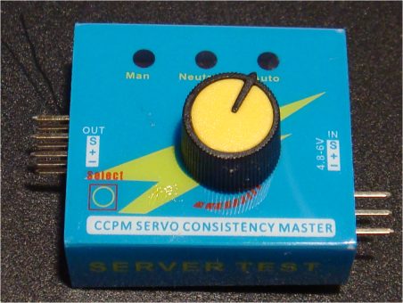
Servo Tester
Kit is available from
Talking Electronics for $15.50 plus $6.50 postage.
Click HERE
to buy kit.
|
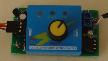
This project has 5 different names and 5 different uses.
It is also know as, and is used in these projects:
REMOTE BOOM GATES
GRIPPER
SERVO TESTER
CONTINUOUS ROTATION SERVO TESTER
POINT CONTROLLER using SERVO
(these projects are on TalkingElectronics.com
website)
It connects a knob on a potentiometer to a servo so you can control the
output as fast or slow as you turn the knob.
If you fit a continuous servo, the output will increase in RPM as you
turn the knob and rotate in the reverse direction when you turn the knob from
the mid position to the other end.
A CONTINUOUS ROTATION SERVO is different from a normal servo and you
need to read our CONTINUOUS ROTATION SERVO project to understand how it
works.
The project uses a CCPM servo control module that allows you to control
the output of the servo as slow as you like, via a pot on the module.
This module fits on top of the printed circuit board via connectors and
has a power supply to deliver 5v5 to the module.
The board can be mounted with 4 screws before the module is fitted and
you can provide 12v AC or DC and the project will work.
The input voltage can be as low as 9v AC or DC, but not higher than 12v
AC or DC as the regulator transistor will get too hot.
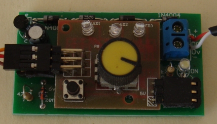
CCPM SERVO MODULE
The heart of the project is a SERVO CONTROL MODULE.
It is fitted to the Printed Circuit Board with stand-offs (connectors).
The images below show the CCPM SERVO MODULE with plastic cover.
The next images show the connectors fitted.
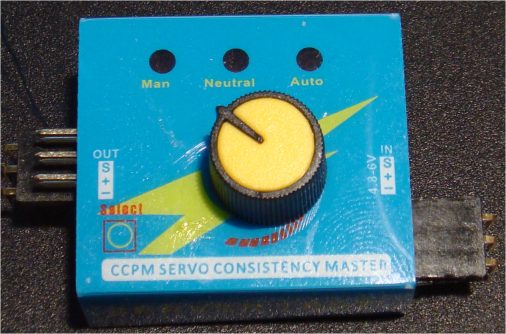
Module with 90° connectors attached
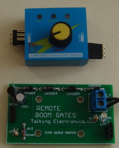
CIRCUIT:
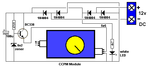
The circuit has been drawn to follow the components on the board to make
it easy to see what the components do.
The 4 diodes are a bridge to allow either AC or DC and it does not matter
which way the power leads are connected.
The transistor produces a 5.5v rail for the CCPM module. One or two
servos can be connected to the pins on the left-hand-side. We have only
shown one set of pins on the circuit - but there are two sets.
Rotating the control knob will activate the output of each servo at the
same time.
CONSTRUCTION
All the parts fit neatly on the PC board.
The transistor, diodes, electrolytic and LED are identified on the
board and must be fitted correctly.
The screw terminals allow the board to be easily wired to your
layout. The 2-connector block goes to the power supply.
HOW IT WORKS
Once everything is connected, the control knob on the CCPM
Module will turn the arm on the servo clockwise or anticlockwise at the same speed
as you turn the knob.
The module has a SELECT button that activates the servo automatically
and moves the output fully in one direction and then the other and
constantly repeats. Pushing the button again makes the servo go to
centre position and stay there.
|
PARTS LIST
$15.50 plus $6.50 postage.
Click
HERE
to buy kit |
1 - 470R
1 - 4k7
1 - 100u 25v electrolytic
4 - 1N 4004 power diodes
1 - BC338 transistor
1 - 3mm white LED (high bright)
1 - 6v2 zener
2 - 3pin male headers 90°
2 - 3pin male headers
4 - 3pin female headers
1 - CCPM Servo Control Module with pot
1 - 2-Connector screw-terminal block
1 - Remote Boom Gates PC Board |
| Email me with any changes or
improvements or additions you would like to be included:
Colin Mitchell
These projects are also on Talking Electronics.com website and will
contain more information.
1-11-2017
|