A SIMPLE SINGLE BOARD
THROTTLE
![]()
The Throttle
has an output of 0v to 12v at 700mA with M-2155 transformer and 1.4amp with
M-2156
transformer. The mini pot mounted on the board has a scale to show
the approximate output voltage and this voltage represent the approximate
percentage of the speed of a 12v motor. The mini pot can be with a standard pot on the front of a
case, depending on the application for the project. You can also
include an ammeter if you wish.
Most commercial train controllers contain a transformer and a wire wound
rheostat. The transformers often have an uncontrolled DC or AC output as well
(a direct output). Extra control units can be added to these train controllers, allowing
independent control of two trains, on different tracks, simultaneously.
This
simple throttle is ideal as an add-on throttle for the control of shunting
yards or a second main line. It can also be mounted in a box with its own
transformer, as a stand-alone unit.
Construction has been kept very simple by the use of a printed circuit
board. Nearly all the components, including the heatsinked BD 679
transistor, have been mounted on the PC board, leaving only minimal external
wiring. The only external components are the switch for changing the direction
of the train.
Not having enough throttles is one of the most frustrating things for a
railway modeller. The main lines each require their own, and it is really handy
to have at least one more to use for shunting. If you have set up your layout to
have blocks, you may even like one per block.
Alternately, if you want a throttle with momentum, it can be easily achieved
by the addition of an electro, a resistor and a switch. More complex brake and
throttle arrangements can be lashed up with a few components. Using the basic
momentum circuit, it is possible to remove the speed control pot altogether,
using two push buttons in its place, one for acceleration, and one for braking.
If computer control is what you are after, the throttle may be controlled
either by a digital-to-analog converter, or by selecting different voltage
levels from a divider chain using a 4051 analog multiplexer. In the second case,
there will be only eight speeds available, but if the momentum circuit is used,
it will smooth out the steps, making the transition from one speed to the next
undetectable. The reversing switch will need to be replaced by a relay.
|
The Throttle circuit diagram. |
|
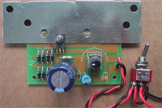
The complete Throttle showing the placement of the components |
HOW THE CIRCUIT WORKS
The throttle can supply 1 to 2 amps depending on the transformer used. The diodes in the bridge have been paralleled to form a 2amp bridge. The
electrolytics will not be needed in all applications of the throttle and in
most cases can be omitted. The pulse action of the un-smoothed DC can be
beneficial to the starting of some motors.
This throttle does not have any overload protection built into it. If you
feel that protection is necessary, there are two simple ways of providing it.
One is to put a 1 or 2 amp fuse in line with the output, depending on
both the transformer rating and the maximum current your engine should
draw. The other is to put a 12v car headlamp or brake light bulb in line
with the output. The best way to choose a bulb for this application is to try them.
First the mains voltage is reduced to a usable level by the transformer. Two
different low-cost transformers can be used. The M2155 is a 1 amp type and
M2156 is a 2 amp type. This is the AC rating and when you connect any
transformer to a DC power supply circuit you must de-rate the current rating by
30% to give the maximum DC current that can be delivered by the power supply.
The reason for this is, the AC voltage is increased by 40% when it is
rectified and to maintain the VA (volt-amp) rating for the transformer, so the
current rating must be decreased.
This means the 1 amp transformer will produce a 700mA power supply and the 2
amp transformer will produce a 1.4 amp power supply.
For a low-cost Throttle this output is quite sufficient and is all you can
get, as quite a lot of heat will be developed in the diodes, transistor and
transformer when 700mA is flowing and literally burn your fingers when 1.4 amps
flows.
The BD 679 regulator transistor must be heatsinked because there is more
than 100-200mA required and you will certainly need a large heatsink when the
full rated current flows.
The heat generated in the transistor is due to two factors. One is the
current flow. Obviously, as more current flows, the transistor will get hotter.
But the other factor is the voltage across the transistor. If you are drawing
100mA at 12v, the transistor will rise to a certain temperature. If you reduce
the output to say 6v, while still drawing 100mA, the transistor will get hotter
because the voltage across it will be greater. In the first case the voltage
across the transistor will be the voltage from the bridge rectifier minus the
output voltage. Our figures were 22v - 12v = 10v across the transistor.
In the second case the voltages are: 22v - 6v = 16v
In the first case the transistor will dissipate 1 watt and in the second
case 1.6 watts.
This is a 60% increase and is one of the hidden factors behind
heat-generation in a power supply.
Both transformers have a 15v AC output and the diode bridge rectifies this
voltage. The output of the bridge is termed un-smoothed DC and if used to power
an amplifier, for example, it will produce a very loud buzz from the speaker.
This un-smoothed DC is then fed to an electrolytic. This can be bypassed
for an un-smoothed DC output by not fitting the electrolytics to the PC
board during construction. The function of the
electrolytic is to charge on the voltage peaks of the un-smoothed DC, then
discharge into the load during the time between the peaks, this smoothes the
DC. The voltage will still fluctuate a small amount during the charge/discharge
cycle and if you connect it to an amplifier, a small amount of annoying
background hum will be produced. This 'hum’ will be greatest when maximum
current is required as the electrolytic is not capable of delivering enough
energy during peak requirements and the waveform becomes rippled. The only way
to improve this is to put high value electrolytics on the board or use a simple
electronic regulator in the form of a transistor.
The Darlington transistor in the output is capable of delivering the varying
current while maintaining a constant voltage. It does this by having a voltage available to it from the bridge rectifier in the form of
about 22v, even though it supplies the output with a voltage up to 12v. The
voltage on the output is adjustable from 0v to 12v, via a 5k pot.
The pot gets its voltage from a zener regulated source and you can pick off
any voltage from 0v to 12v via the wiper. This stable voltage is fed to the
base of the Darlington transistor. The transistor is wired as an
emitter-follower. You can think of the transistor as a low resistance that
automatically varies according to the current requirement of the output.
If the load requires additional current, the normal effect would be for the
output voltage to drop according to ohms law. But what happens in this case is the drop in output voltage turns
on the transistor so that it delivers the extra current from the power rail. In
doing so, the voltage may fall by as much as 2v to 3v on the power rail but the
output does not see this as the regulator transistor is separating the voltage
on the power rail from the output.
CONSTRUCTION
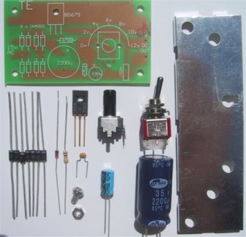
|
The Throttle kit |
|
PARTS LIST: |
|
1 - 470R |
|
EXTRAS: |
|
1 - heatsink compound (small amount) |
All the components fit on to a small PC board with the transistor at the
edge of the board so that it can be screwed to a heatsink.
Fit the 8 power diodes first. These all align in the one direction and the
line on the board corresponds to the white or silver band on the body of the
diode.
Next fit the resistor, zener diode and 100n monoblock capacitor. The zener
looks like a signal diode and may have a number of different markings on it.
Sometimes it is marked with the zener voltage and sometimes it has a code
number. It may have 1N 5535 or 1N 5245 or 1N 5861 or even another number. Zener
diode numbering is very messy, but they all refer to a 15v zener. The mini pot
is next to be fitted. If you want to mount the pot on the front panel, it will
be best to use a standard 5k pot with shaft so you can fit a knob.
The two electrolytics are next, making sure the positive lead goes down the
hole marked on the overlay. You can leave the electrolytics out of
the circuit for an un-smoothed DC output.
Finally, the BD 679 is fitted so that the heatsink goes between the
transistor and PC board (to provide the best heat transfer). See below for more
details on choosing the correct heatsink and applying thermal grease to improve
heat transfer.
An adequate heatsink is most important when building a Throttle, both to
make it reliable and keep the components operating within their temperature
range.
When any of the parts get too hot you can introduce unwanted hum (another
name for ripple) or even create premature failure of the diodes or transistor.
When all the components are fitted, and the heatsink is in place, it can be
placed in a suitable case, along with the power transformer, make sure the
heat sink is well ventilated.
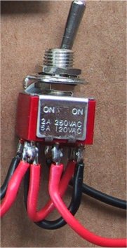
|
A close up of the Throttle direction reversing switch |
MAINS OPERATION
This project has two options. It can be a mains operated project, using a
2155 or 2156 transformer or it can be connected to a plug pack.
We recommend it be connected to a 16v AC 1 amp plug pack as these are double
insulated and provide complete safety for the constructor.
As we have mentioned in the introduction, the 2 amp transformer M 2156 will
not provide much more than 1.4 amps DC output so the 1.5 amp AC plug pack has
nearly the same rating.
By the time you buy a M 2156 transformer and power cord, the total will be
the same as the cost of the plug pack so it should be one of your
considerations.
HEATSINK
The heatsink is one of the most important components for this Throttle
because of the amount of current passed by the
transistor, (up to 2amps). It must provide adequate heat dissipation to
protect a heat-sensitive device, from being damaged.
All throttles dissipate heat. Some are more efficient than others but
whenever voltage and current are present together, heat will be
dissipated.
The heatsink in our project fits between the metal side of the transistor
and PC board to get direct contact with the transistor.
It is most important to get good thermal contact so that any heat generated
in the transistor will be carried away by the heatsink.
Since the transistor has a very small area for heat transfer, (all the
heat must pass through the side of the transistor) it is most important that
the gap between the face of the transistor and the heatsink be filled with
thermal grease (thermal compound). You only need a small amount smeared over
the face of the transistor. The bolt is then passed though the transistor,
heatsink and PC board and the nut tightened until a small amount of grease is
squeeze out from under the transistor. This proves the nut is tight but it must
not be too tight as you may damage the transistor itself by cracking the case.
Don't use ordinary grease, as it doesn't have the heat transfer characteristics
we need.
SIZE OF HEATSINK
The way to select the correct-size heatsink is to build the project and fit
a heat sink about 4cm x 10cm as a trial experiment. Next you need some high
wattage resistors or car lamps to load the power supply to its maximum rating
(this will depend on the transformer you use).
Place one finger on the transistor and another on the heatsink, about 2cm
from the transistor, and monitor the temperature rise of both positions. You
should be able to hold your fingers on both for the duration of the experiment.
If not, a thicker heatsink will be needed, as the one you are using is not
transferring the heat away from the transistor fast enough.
HOUSING
The project should be housed in a small case, preferably plastic, with
either a flying lead on the output or a set of terminals on the front of the
case, marked with positive and negative.
The power cord must be anchored inside the case so that it cannot be pulled
out.
You can place a metal plate in the inside of the bottom of the case to act
as a chassis and this can be bent to form part of the heatsink for the
transistor.
If you are going to use a plug pack, the case will be a lot smaller, and a
lot cheaper. You could even leave the project out of a case and use the mini
pot on the board as the speed/voltage adjustment. I prefer to leave things in
their skeleton form, so I can see the "works" - that's why I hardly
ever suggest fitting them
into cases.
Decide carefully which arrangement you are going to choose. Either way it
will be a handy addition to your layout
or as a piece of test equipment.
The kit for this project can be
purchased from Talking Electronics.