|
|
|
|

You can add this circuit to all sorts of projects that require on-off control.
Our design allows up to 4 touch sensors using a PIC12F629. The output of each touch sensor is active LOW and this can be connected to an additional circuit to control a LED, motor or relay etc.
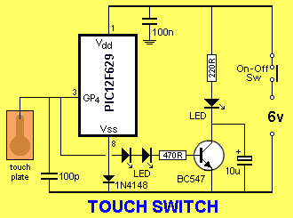
The photo of the project shows one output with the two LEDs connected in
series to produce an infinitely high input impedance so that one of the
input/output
lines of the micro can be used as both input and output. Two LEDs drive the base
of a transistor and a third LED is connected to the collector of the
transistor to indicate it is being activated.
The input lines to a PIC microcontroller contain FETs and a FET has an
almost infinite input impedance (resistance). This mean it is very
sensitive and will detect voltages
that are called STATIC ELECTRICITY.
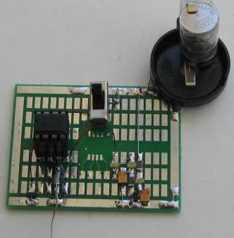
The Prototype PC board with one
input
These voltages (Static Electricity and radiation from power cables and
wiring) are all around the home and are produced by a number of
things including the electromagnetic radiation from the 110v or 240v
mains wiring, the radiation from a TV that uses a picture-tube (Cathode
Ray Tube) by the electrons being fired by the gun towards the screen, the static produced when walking on carpet or produced by
clothing hen it is moved on the body and the movement of paper and plastic items.
You will be amazed at where static electricity can be found and the
input to the microcontroller we are using in this project will detect
these charges, simply by connecting a wire to one of the input pins.
In fact the micro is so sensitive it will react uncontrollably when
moved around the home.
The whole essence of this project has been to remove the
uncontrollability-factor and create a touch wire that will only respond when
it is touched.
This is a very difficult thing to do as we are using the very sensitive
input of a pin to detect the charge (or lack of charge) produced by a
finger and at the same time masking the charge from the surroundings.
The answer is to charge a small capacitor and see if the finger
discharges it. This means the input will not be responsive to any static
charges in the room.
For this to work, we are assuming the body is uncharged and some-times
clothing etc will create a charged condition and the touch sensor will
not work.
That's why this project will not work in all situations and with all
users.
However when it does work, it is amazing.
The slightest touch of the wire with a finger will turn on the LEDs.
You can build 1, 2, 3 or 4 sensors and use them with touch pads to
control all types of devices.
One of the clever features of this circuit is the use of a single input/output line
as both an input and output.
This is called multiplexing or "sharing."
The line is firstly set up as an output and the 100p capacitor is
charged. It is then turned into an input line and a 20mS delay is called to
give a short period of time for a finger to discharge the capacitor.
The charge on the capacitor is then detected after this time and if it is low, the line
is turned into an output to activate the base of the transistor via two
LEDs.
These LEDs have been included to produce an infinitely high impedance on
the line so that the charge on the 100p capacitor will not be affected.
The two LEDs and base-emitter junction of the transistor will produce an
infinite impedance to voltages below the turn-on voltage of the
combination.
Another clever circuit-design is placing a diode between the "ground" or
Vss line of the micro and the 0v rail.
This reduces the 6v supply to 5.4v (as this is the maximum voltage the
chip can be delivered). But more importantly it increases the sensitivity
of the input line and makes the project much more sensitive by actually
raising the zero-detection-point by about 0.5v.
|
INSTRUCTIONS FOR
USE Touch the Touch Plate or wire and allow the capacitor to discharge. The LED corresponding to the sensor will illuminate and the transistor will sink up to 100mA. |
CONSTRUCTION
GOING
FURTHER
Touch
Switch
16/10/10
The circuit can be built on any
type of Proto board. We have used one of our surface-mount PC boards as
all the components and wiring can be seen at the same time and this
makes construction and diagnosis easy.
The photo shows only one input however the board is big enough to add
the three other sections.
The
PROGRAM
This project is part of a course in PIC Programming. See left
index on Talking Electronics website: List of PIC
Projects: for the projects in this course.
The course consists of
building these projects and modifying the programs to learn the art of
programming PIC microcontrollers.
Here are the files you will need for "burning" your chip and/or
modifying the program:
TouchSw.asm
TouchSw.txt
TouchSw.hex
The following program is for viewing. It may contain
spaces or hidden characters that will not compile correctly to produce a
.hex file. Use the .hex file above to burn your chip or the .asm file to
modify the program.
;*******************************
;Touch Switch.asm
;13-10-2010
;***********************
	list	p=12F629
	radix	dec
	include	"p12f629.inc"

	errorlevel -302	; Don't complain about BANK 1 Registers

	__CONFIG	_MCLRE_OFF & _CP_OFF
		& _WDT_OFF & _INTRC_OSC_NOCLKOUT  ;Internal osc.

;_MCLRE_OFF  - master clear must be off for gp3 to be input pin

;****************************************************************
; variables - names and files
;****************************************************************

temp1	equ 20h	;
temp2	equ 21h	;
temp3	equ 22h	;
temp4	equ	23h	;
_flash     equ	24h	;

;****************************************************************
;Equates
;****************************************************************
status	equ	0x03
rp1	equ	0x06
rp0	equ	0x05
GPIO 	equ 	0x05


status		equ	03h
option_reg	equ 	81h


	; bits on GPIO

pin7	equ	0	;GP0
pin6	equ	1	;GP1
pin5	equ	2	;GP2
pin4	equ	3	;GP3
pin3	equ	4	;GP4
pin2	equ	5	;GP5


	;bits

rp0	equ	5	;bit 5 of the status register

;****************************************************************
;Beginning of program
;****************************************************************
	org	0x00
	nop
	nop
	nop
	nop
	nop
SetUp	bsf	status, rp0 	;Bank 1
       	movlw	b'11101000'	;Set TRIS  GP1,2,out  GP5 in
	movwf	TRISIO	   	   ;
	bcf	status, rp0	;bank 0
	movlw   07h         	;turn off Comparator ports
        movwf   CMCON       	;must be placed in bank 0
        call	flash
	clrf 	GPIO       	;Clear GPIO of junk
	goto 	Main

;****************************************************************
;* Delays 			*
;****************************************************************

_10us	goto	$+1
	goto	$+1
	goto	$+1
	goto	$+1
	retlw 	00

_250uS	movlw	.80
	movwf	temp1
	decfsz 	temp1,f
	goto 	$-1
	retlw 	00


_1mS	nop
	decfsz 	temp1,f
	goto 	$-2
	retlw 	00


_10mS	movlw	.10
	movwf	temp2
_10	nop
	decfsz 	temp1,f
	goto 	_10
	decfsz 	temp2,f
	goto 	_10
	retlw 	00


_20mS	movlw	.20
	movwf	temp2
_20	nop
	decfsz 	temp1,f
	goto 	_20
	decfsz 	temp2,f
	goto 	_20
	retlw 	00


_250mS	movlw	.250
	movwf	temp2
_250	nop
	decfsz 	temp1,f
	goto 	_250
	decfsz 	temp2,f
	goto 	_250
	retlw 	00

;****************************************************************
;* Sub Routines 			*
;****************************************************************

	;flash LED at start-up

flash	movlw	0ffh
	movwf	_flash
	bsf	gpio,1
	nop
	decfsz	_flash,1
	goto	$-2
	bcf	gpio,1
	retlw	00

;****************************************************************
;* Main 							*
;****************************************************************

Main	bcf	gpio,4		;make line LOW to discharge 100p
	call	_10uS
	bsf	gpio,4		;make line HIGH to charge 100p
	bsf	status, rp0 	;Bank 1
       	movlw	b'11111000'	;Set TRIS  GP4 in
	movwf	TRISIO
	bcf	status, rp0	;bank 0
	call	_20mS
	btfss	gpio,4
	goto	$+3
	bcf	gpio,2
	goto	Main
	bsf	status, rp0 	;Bank 1
       	movlw	b'11001000'	;Set TRIS  GP4 out
	movwf	TRISIO
	bcf	status, rp0	;bank 0
	bsf	gpio,4		;turn on LEDs and transistor
	call	_250mS
	goto	Main

	END
You can add additional features to this
project by writing your own program or adding to the program above. Send any additions to Talking
Electronics for inclusion in this article.
Parts List
Cost:
au$15.00
plus postage
Kits
are available
4 -
220R SM
resistor
4 -
470R SM
resistor
4 - 100p SM capacitors
1 - 100n SM capacitors
4 - 10u SM electrolytic
12 - SM yellow LEDs
1 - SM diode
4 - BC847 SM transistors
1 - SPDT mini slide switch
1 - 8 pin IC socket
20cm fine enamelled wire
10cm tinned copper wire for touch wires
20cm - very fine solder
1 - PIC12F629 chip (with
Touch Sw routine)
1 - battery holder
4 -
button cells
1 - Prototype PC board