|
TRACK TESTER |
|
|
This project shows
the polarity of the track as well as providing an indication of the
voltage. You don't need an accurate measurement but it's handy to know
if the voltage is above or below the ideal operating conditions.
You can also see the track is DCC as both red LEDs will illuminate
and the piezo will produce a tone.
The kit costs less than a ready-made product and has more features.
Here is a Track Tester on eBay. It just shows the voltage on 3 LEDs and
costs $18.00:
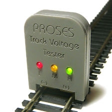
Track Tester showing the voltage
and polarity
Close-up of TACK TESTER
Our kits has more features and costs $14.50 posted.
THE CIRCUIT
CONSTRUCTION
U
PROGRAMMING
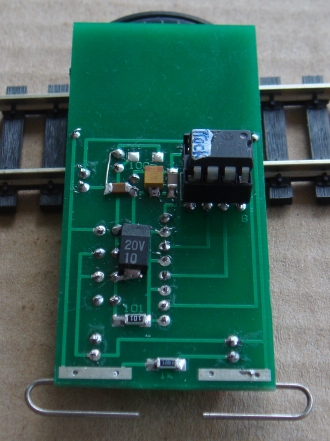
Back of tester showing the
microcontroller
and surface-mount components
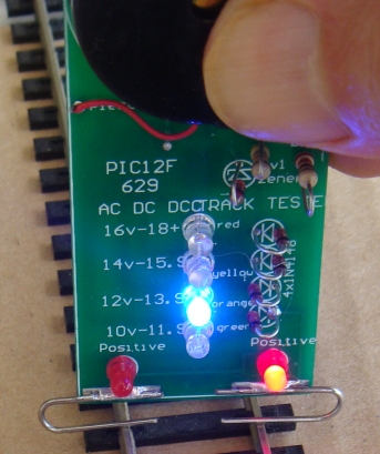
THE LEDs
The voltage on the track is shown by a set of
4 LEDs. You don't need to know the exact voltage but if the voltage is
higher than 18v you need to be aware as this will damage some
electronics modules and below 10v will indicate a fault somewhere in the
system.
The LEDs are arranged in 2v increments and two LEDs will flash when the
voltage is between two LEDs:
The 16 - 18v LED flashes when the
voltage is higher than 18v.
Two LEDs flash when the voltage changes
from one LED to the other.
No LEDs illuminate below 10v.
The circuit has two red LEDs to indicate the positive track and a
voltage detector to convert the voltage to one of the LEDs in the BAR
GRAPH. This means you can put the tester around either way and
will produce the correct results.
Our project is quicker and more convenient to measure the voltage with the
spring-contacts.
The project is 
The other Loud Mobile Ring
Circuit
Place the tester on the rails and the springy terminals will
make contact. One of the red LEDs will illuminate and one or more of the
LEDs in the BAR GRAPH will indicate the voltage.
The piezo diaphragm will buzz or hum if the track is DCC.
It will also buzz if the track is DC but has a lot of "ripple." This
means the smoothing electrolytics in the power supply are not working to
produce SMOOTH DC. This may be the reason why DC motors are "humming"
This project is part of a PIC
microcontroller course to teach programming.
The kit comes with a pre-programmed microcontroller and you just have to
solder the kit and it is ready to work.
However there are a number of constructors who will be using this
project to help them understand how to program a microcontroller and
this section is part of the PIC micro course.
Before choosing a PIC we tried zener diodes and resistors to turn ON the LEDs
at different voltages, but the result was very poor. It was very
difficult to get them to turn ON at the desired voltage and turn OFF at
a higher voltage.
We could have used a LED BAR GRAPH chip but it does not have the
flashing feature to show when the voltage is midway between each range.
A micro is small, cheap and is a lot more versatile and anything else.
All you have to do is write an A-to-D program to detect the voltage.
This requires just a single input/line, a 100n capacitor and a high
resistance resistor.
The micro discharges the capacitor at the beginning of the cycle then turns the line into an INPUT.
It then calls a very short delay and looks to see if the
capacitor has charged to about 3v. This voltage is detected by the micro
as a HIGH. If the input line is not HIGH, the program calls the short
delay again and looks for a HIGH.
A file is incremented every time the delay routine is called.
The lowest voltage we need to detect is 9.9v and this resulted in about
40 delay loops. As the voltage is increased, the number of delay loops
decreases, so that 18.9v resulted in 19 loops.
The whole secret to setting up this "test-routine" is to get a delay
routine that is short-enough to result in about 4 loops for every volt
increase.
We used an adjustable voltage bench power supply and the delay routine was shortened until we got about 4
loops for each volt. This allowed us to detect
each 250mV increments.
Once we have a table of loops for 9.9v to 18.9v we had values from 19 to
40.
All we have to do is put these values into a sub-routine so that each
value produces a result on the "bar graph."
You must remember this: You do not know what value will be produced by
the micro so all values must be handled and a result on the display must
be produced. Otherwise the micro will jump to the wrong part of the
program.
The value of loops we get is called RAW DATA and we must "clean it up"
by removing the values 1 -19. The first instruction subtracts 19 to get a result of ONE to TWENTY.
This means we now have to allocate 20 values to the display in which the
the value of ONE represents 18.9v.
Every value
must go to a LED or a pair of flashing LEDs.
We now decrement "loops" and if it zero, we know the result is 18.9v.
This means we flash the top LED.
If the answer is not zero, the micro goes down the sub-routine and
decrement the value again. If it is zero, the top LED is turned ON.
The sub-routine keeps decrementing "loops" and turning on one of the LED
or flashing two LEDs, until "loops" is decremented to zero.
|
|
|
20/1/2015