
800m (2400ft) FM transmitter that fits on top of a 9v battery.
Page 1
P2
This is one of the smallest and neatest FM transmitters to be presented
as a construction project and it has the advantage of being available
as a complete kit of parts. This will save going to a number of suppliers
as no single supplier has all the necessary components.
The circuit has been specially designed to demonstrate the techniques
of FM transmission and to start you in the world of surface-mount
assembly.
FM transmission is the best mode for transmitting a signal as it does
not suffer from interference such as electrical noise from car engines
or electrical appliances etc. It also achieves the greatest range
with the least power.
With just a handful of components and a few milliwatts of output power
you can produce an FM transmitter with a very impressive range and
perfect clarity.
The Voyager MkII kit and
LED Power Meter is available from Talking Electronics

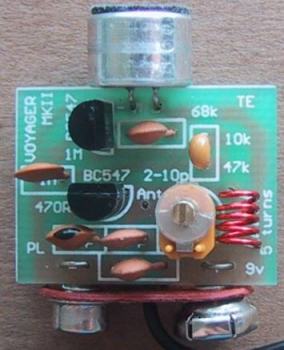
The circuit diagram for Voyager
Mk II.
|
SUMMARY OF SPECIFICATIONS |
|
Supply: 9 volts Current consumption: 7mA Battery life: 50 hours ZnC 100 hours alkaline Tuning range: 80 - 110MHz (by stretching or compression the oscillator coil) Fine tune by adjusting the air trimmer (2MHz adjustment) Stability - Low. Bug to be left in-place and not to be moved or handled. Antenna length - 175cm (5ft 9in) |
With a 175cm (5ft 9in) (half-wave antenna) supplied in the kit, the range has been conservatively rated as 800 metres (2400ft) under normal working conditions. In many countries you must reduce the
maximum range to 30ft (10metres) by cutting the antenna to 10 inches. If this is the case, you must abide by it. Some countries totally ban these brilliant devices. You need to find out the situation in your own locality.To introduce surface-mount technology to our range of projects, we have started with resistors. These are the easiest of the surface-mount components to identify and fit.
Some of the other components such as capacitors and transistors are so small they are almost impossible to solder by hand and surface-mount capacitors are not marked in any way so they become easily mixed up if you are not very careful.
Surface-mount technology is entirely different to normal through-hole placement and some of the differences are explained in this article.
The major difference is size and if you are having trouble soldering 1/4 watt resistors, you will have ten times more difficulty with surface mount. SM items are so small it takes the keenest eyesight to read the figures on the component and the nimblest of fingers to pick them up and place them.
But until you buy a kit and see what the parts look like, you will have no idea if you will be able to cope.
Nevertheless surface mount has arrived and is here to stay. Most modern designs already include surface mount components and many are already entirely surface mount. Take pocket cameras, watches, pendant transmitters, toys, video recorders, video cameras and computers for example. Their miniaturisation has been almost entirely due to using smaller componentry.
Surface mount is very easy to implement on a large scale as the components are available in large quantities on reels or in tubes but when it comes to a one-off project, things are different. Few suppliers sell individual surface-mount components and some sell them in lots of 10 or 100. The normal purchase for surface-mount is on a reel of 1,000 to 5,000 pieces.
The only solution is to provide a kit and to make it easy for everyone to put together, we have just converted the resistors to surface-mount.
Some of the other components are not available in surface-mount (such as the coil) and there is no real advantage in converting everything to surface mount as the battery cannot be reduced in size without reducing the number of hours of operation.
The main difficulty with surface mount is placing them on the printed circuit board and holding them in place while soldering. There are a number of aids to help you do this, such as solder pastes and solder creams, silicon and infra-red setting glues but most of these come in syringes and cost as much as $20 for a 1oz (30gm) tube. For a simple project, this additional cost is out of the question.
To keep costs down we are going to hand solder each resistor without the aid of glue and the technique we use is called RE-FLOW SOLDERING.
Re-flow soldering only requires two hands. Normal soldering requires three hands - one to hold the component in place, one to hold the soldering iron and one to hold the solder. If you have three hands available, (such as the help of an assistant), you can use the normal soldering method.
Basically re-flow soldering consists of heating up the solder on the board AND THE END OF THE RESISTOR AT THE SAME TIME so that the resistor makes a perfect connection to the board. This is discussed fully in the soldering section.
HOW THE CIRCUIT WORKS
The circuit consists of two stages - an audio amplifier and an RF oscillator.
The electret microphone contains a FET transistor and can be counted as a stage, if you wish. The microphone detects audio in the form of air vibrations that enter the hole (at the end of the mic) and move the diaphragm. This diaphragm is a thin piece of metallised plastic such as mylar and is charged with electrical charges during manufacture.
Next to this is a metal plate containing a number of holes so that the air readily passes through. The relative distance of the mylar diaphragm to the metal plate makes the charges move on the diaphragm (remember static electricity theory: like-charges repel and unlike-charges attract). Some of the charges pass down a lead that touches the metal plate and into a FET amplifier - it looks like a three legged transistor. The FET amplifies the charges and gives a reading on the output lead.
The output must be connected to a supply via a resistor called the load resistor. The FET draws a varying current during its operation and this creates a varying voltage on the output (across the load resistor).
The reason why a FET has been used is due to it having a very high input impedance and does not have any loading effect on the charges.
The output waveform from the microphone will be typically 3 - 30mV in our case, depending on how close it is to the source of the sound. The circuit is capable of detecting a whisper at 10ft (3M) and only very sensitive microphones have been included in the kits.
You can also get medium and low sensitivity devices from suppliers so you have to be careful as they are not labelled.
A 22n capacitor on the output of the microphone couples the signal to the input of the first audio amplifier stage. This capacitor is designed to separate the DC voltage on the microphone from the base voltage on the transistor.
The first transistor stage consists of transistor and two biasing resistors.
The stage is said to be "AC coupled" as it has a capacitor on both the input and output so the DC voltages of the other stages do not influence the voltage on the stage.
The stage is also said to be "self-biased" with the 1M base resistor turning the transistor on until the collector voltage drops to about half rail voltage. The value of the base resistor is chosen so that this occurs.
The value can be chosen by experimentation. If the value is too low, the voltage on the collector will be below half rail. If it is too high, the collector voltage will be too high. The AC gain of the stage is about 70 and the signal is amplified and passed to the oscillator stage via a 100n capacitor.
The signal is now typically 200mV to 2,000mV in amplitude and this is adequate for injection into the oscillator stage.
The oscillator stage is designed to operate at about 100MHz and this frequency is set by the value of inductance of the 5 turn coil and the capacitor(s) across it. The 39p and air trimmer can be considered as a single capacitor. The frequency is also determined to a lesser extent by the transistor, the 10p feedback capacitor and also the 470R emitter biasing resistor and the 47k base bias resistor. The supply voltage also has an effect as the oscillator can be classified as voltage controlled.
There are a lot of things that set the frequency and even though the parts have a 5%, 10% or even 20% tolerance, they are STABLE at their present value. The 10p and 39p are NPO types and this means they are stable even when the temperature changes a small amount. The frequency is firstly set by pushing the turns of the coil closer together to lower the frequency or pulling them apart to raise the frequency and then the air trimmer is adjusted to obtain the precise frequency required. The air trimmer has a range of about 2MHz.
The circuit will stay at the desired frequency providing the supply voltage remains constant and the temperature of the parts do not rise appreciably (such as when the project is left in the sun etc).
Voyager MkII is not designed to be handled and is not suitable to be worn on the body. It is designed to be placed on a shelf and left in position.
The most important components in the oscillator stage are the coil and capacitor(s), making up the parallel tuned circuit.
They do almost all the work in setting the frequency and generating the waveform. The transistor merely turns on at the correct instant in each cycle to deliver a small amount of energy to the tuned circuit.
How this is done: The transistor is firstly turned on via base-bias resistor and it injects a small amount of energy into the parallel tuned circuit. A few low-amplitude cycles now take place and we pick up the operation when the tuned circuit is operating at full amplitude and producing a sinewave at about 100MHz. This frequency is called the CARRIER.
The parallel tuned circuit is also called a TANK CIRCUIT and the name was coined during the development of the earliest transmitters where it was found a coil and capacitor in parallel would smooth out electrical pulses like filling a water tank in bursts so that it delivers an even flow of water.
This name has stayed with us and is an ideal way of describing a coil/capacitor combination.
The waveform from the tank circuit is passed to the 10p and this modifies the voltage on the emitter of the transistor.
There are two ways of turning on a transistor. One is to raise the voltage on the base while holding the emitter fixed and the other is to hold the base rigid while lowering the voltage on the emitter.
The second method is used in this circuit and the 10p moves the emitter up a very small amount at the rate of 100 million times per second to turn the transistor off.
The base is held rigid via a 1n capacitor and this value is sufficient to hold the base rigid at 100MHz but allows it to move up and down at audio frequencies so that audio being processed by the first transistor can be passed to the oscillator.
The oscillator transistor does not determine the waveshape of the signal, it mainly delivers a pulse of energy to the tank circuit at the correct instant where the coil and capacitor do all the work in creating the carrier signal. There is one more feature of the tank circuit. Even though it is injected with a pulse of energy of only a few millivolts, it is capable of producing a higher amplitude waveform on its output. In other words the tank circuit is capable of amplifying the voltage supplied to it. This is called its Q-factor.
The other two components in the stage are the 47k base-bias resistor and 470R emitter resistor. The 47k turns the transistor on when the power is first applied and sets the operating point for the stage. The 470R emitter resistor acts as a current limiting resistor and allows the transistor to be injected via the emitter.
The voltage produced by the tank circuit is monitored by the 10p and passed to the emitter of the transistor. During a portion of the cycle, the voltage it delivers, turns the transistor off. This effectively removes the transistor from the circuit and allows the waveform from the tank circuit to be passed to the antenna.
When a waveform at 100MHz is passed into a wire (such as an antenna) the signal is very easily radiated as electromagnetic energy. This is how the signal is radiated to the surroundings.
The 22n supply capacitor across the battery is designed to tighten up the power rails. The power rails have also been kept tight by connecting the battery directly to the printed circuit board.
Note: The circuit will not operate from a power supply without generating a lot of "mains hum" - the annoying 100 or 120 cycle hum from the mains - you must use a battery to get a crystal clear, hum-free, output.
Test voltages have been provided on the circuit diagram to help with servicing. They are only approximate and apply to our prototype. They show how each transistor has a voltage on the base of about 0.6v, with respect to the emitter, to turn it on.
The voltages around the oscillator stage cannot be measured with an ordinary multimeter when the circuit is operating as the leads of the multimeter will act as an antenna and kill the operation of the circuit. This is certainly the case on the emitter of the second transistor, where the leads of a multimeter will draw off so much energy that the stage will stop working.
Because you cannot detect the operation with a multimeter, we have developed a piece of test equipment called a LED POWER METER. This is covered below and shows how the output of the high frequency RF oscillator stage can be measured without loading it too much.
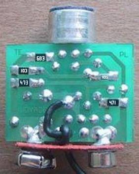
 Enlarged overlay and the
trackwork for the Voyager MkII circuit board
Enlarged overlay and the
trackwork for the Voyager MkII circuit board
HOW FREQUENCY MODULATION IS ACHIEVED
The audio from the microphone is amplified by the first audio stage
and injected into the RF stage via a 100n capacitor.
This waveform increases and decreases the voltage on the base of the first
transistor
by a small amount and modifies the "set point" or "bias point" for
the stage.
This has the effect of slightly altering the timing of the stage (the
time it takes for one cycle to occur) and the resulting frequency
of the stage is altered very slightly by an amount equal to the frequency
of the audio.
The result is frequency modulation of the carrier.
The 5 chip resistors used in this project are: 470R, 10k, 47k, 68k and 1M
RESISTOR AND CAPACITOR VALUES
Keeping this in mind, we go to the markings for capacitors. The basic
unit for surface mount capacitors is p (sounded `puff').
5% TOLERANCE
The following refers to values
with 5% tolerance:
With the size of resistors and capacitors getting smaller and smaller,
the space for identifying the value is getting less and less.
To make things simple, a uniform numbering system has been adopted
for both resistors and capacitors, consisting of three digits. The
first two digits give the value of the capacitor in p or the value of resistance
in ohms and the third digit is the multiplier.
This brings both capacitors and resistors into the same code and once
you can read the code, you can identify everything.
As an example, we will use a 47k resistor. See the third chip in the diagram
above. The digits are 4 - 7 - 3. The digit "3" represents the number
of zeros to put after the number "47." Thus we get 47,000 ohms.
A 470 ohm resistor is "47" and one zero, thus we get 471 on a chip.
A 10k is "10" and three zeros, thus 103 is written on the chip. A
68k is written "68" and three zeros, thus 683 is written on the chip
and 1M is written "10" and five zeros. Thus the chip has 105 on it.
These are the five values used in the Voyager Mk II.
A 10 ohm resistor is "10" and NO ZEROS, so the marking is 100. I know,
I don't like it either but 150 on a chip is 15 ohms and not 150 ohms.
150 ohms is "151." Surface mount
resistors start at 10 ohms and go to about 1M or 2M2.
A zero ohm resistor (used as a "bridge") is labelled "000."
It's only the range from 10 ohms to 100 ohms that will cause problems.
When you see markings such as 120, 180, 470 etc it is best to check
the resistance with a multimeter, to make sure the resistances are
12 ohms, 18 ohms and 47 ohms.
The tolerance for the above resistors is 5%.
1% TOLERANCE
Chip resistors are also available in a complete range of 1% values.
Full details
for reading these value can be found in our Basic Electronics Course.
If any 1% resistors are included in the kit for the Voyager, they will
correspond to the values shown in the following diagram:
Very few surface mount capacitors are marked but those that have identification
follow the p rule. This means 101 is 100p, and 102 is 1,000p.
Another name for 1,000p is 1n (1 nano). 103 is 10n, 104 is 100n and
105 is 1u.
For those who have to convert from the old system, 1n is 0.001u,
10n is equal to 0.01u and 100n is 0.1u.
For surface mount capacitors, you must think in p. This will allow
you to build any surface mount project in the future.
One point to note: With surface mount capacitors, the size of the
chip is no indication of capacitance. The structure of the chip can
be single layer or multilayer and this affects the size. Also the
voltage rating of the capacitor affects the thickness of the dielectric
and thus the size.
![]()