|
THE WASP |
CONSTRUCTION
|
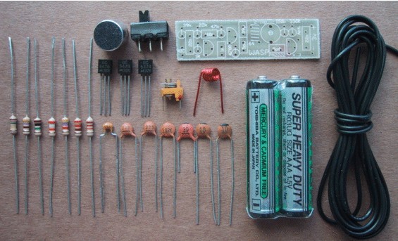
The Wasp components |
|
PARTS LIST 1 - 330R (orange-orange-brown) 1 - 470R (yellow-purple-brown) 1 - 22k (red-red-orange) 1 - 39k (orange-white-orange) 1 - 47k (yellow-purple-orange) 1 - 150k (brown-green-yellow) 1 - 1M (brown-black-green) 1 - 2-10p air trimmer 2 - 10p ceramics 1 - 39p ceramic 1 - 1n ceramic (102) 2 - 22n ceramics (223) 1 - 100n monoblock (monolithic) (104) 3 - BC 547 or 2N 2222 or similar transistors 1 - 6 turn 0.5mm enamelled wire (3mm dia) coil 1 - electret microphone 1 - mini slide switch 2 - AAA cells 1 - 170cm antenna wire Ā 1 - WASP PC BOARD |
A close up of the board showing
the spacing between
ALTERNATE TRANSISTORS
Suitable transistors for this project:
BC 547
BF 180 PN 2222
BC 548
2N
3903
PN 2222A
BC 107
2N 2369A
2N 2897
BC 108
2N 2916
2N 3643 BC 109
BC 182L
2N 4140 2N 2222
BC 184L
2N 4970
2N 2219A
ZTX 300 PN 100
All the components fit onto the PC board shown above. It is very small and
compact. Everything is identified on the overlay and we have provided a larger
version of the overlay so you can read all the legend (the text on the board). The best way to carry out the assembly
is to start at one end and fit each component as you come to it.
Construction is commenced at the microphone end but the microphone is left to last as the
fine leads may break if the microphone is moved too many times.
The first component to add is the 39k load resistor for the microphone. All the resistors
are fitted STANDING UP. Push the leads down the holes and splay them apart slightly so
that the component stays in position, UP CLOSE TO THE BOARD, while the board is turned
over and the leads soldered.
You can place a small piece of blu-tack on the workbench to hold each part in place while
you solder it.
Solder each lead quickly by applying a small amount of fresh solder to the iron WHILE IT IS IN CONTACT WITH THE LAND so that the solder runs over the land and around the lead.
Only by using fresh solder will you get a clean, neat connection as the flux in the
solder cleans the component leads and track-work so the solder can flow over
the joint.
Snip the leads close to the joint, making sure you don't remove any solder as this
may fracture the connection.
This completes the first component. Continue across the board, soldering each part
as you come to it. Take special care when you come to the transistors as they are
temperature sensitive and if they are overheated, their performance will be reduced.
The transistors are also pushed up to the board so that they are no higher than the
rest of the components and this means the leads are very short. If you take too long
when soldering, the heat will run up the leads and damage the junctions.
The best way to determine if you are taking too long is to hold the transistor with
two fingers while soldering. If you have to let go, you are taking too long.
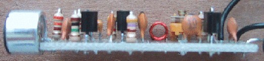
the components and the PC board
Below is a list of alternate transistor that may be suitable for the project.
Almost anything will work in the first stage as it is an audio amplifier and no
"performance" is required. But the high frequency stage is another matter. Many
transistors will work in this stage but the output will vary according to the
quality of the transistor.
Surprisingly, some transistors that work in the oscillator stage will not work in
the output stage.
You will have to do your own research if you intend to build the project from your
own components.
Some readers have said 2N 2222 or 2N 2222N (PN 2222A) work much better than BC 547
but we have not proven this.
However some BC 547 transistors from one supplier will work better than those from
other suppliers - this we have found out!
THE COIL
When you come to the coil you have to do some pre-preparation. It has an enamel
coating on it and this must be removed before it is fitted to the board. The best
way to do this is to fit it to the board and cut the leads so that only 3mm protrudes.
It is then removed and 3mm of enamel removed from each lead by scraping with a sharp knife or razor blade.
The leads are then tinned with a hot soldering iron. The coil is then fitted to the
board and soldered in place. If you
don't remove the enamel before fitting the coil, the project WILL NOT WORK. We have
had many projects sent in with the coil "soldered in place," without the enamel removed.
What has happened is they have not really been soldered at all. The solder has only "GLUED"
the coil in place and the wire has not made electrical contact. Don't let this happen to you.
THE AIR TRIMMER
The air trimmer is the most heat-sensitive component on the board. This is because it has
plastic between the vanes to keep them separated.
The slightest amount of overheating will bend the plastic and prevent the trimmer from
turning. When soldering the leads you must take less than 1 second otherwise the heat
will run up the lead and melt the plastic.
I have seen one constructor go through 6 trimmers before he was successful - a very
expensive exercise. To prevent a disaster like this I can only warn you to be quick
at soldering and leave the trimmer to last so that you don't heat it up when soldering
any of the other components on the same lands.
If you damage it, you will have to buy another.
Ā
THE MICROPHONE
The last component to add to the board is the electret microphone. Make sure the lead
going to the case (this is the negative lead) goes to the negative rail on the board.
Allow the microphone to hang over the edge of the board as shown in the photos. This
will allow the board to fit into a Tic Tac box when completed.
Hold the microphone in your fingers while soldering and if you feel the case getting
hot, you know you have taken too long.
Ā
CONNECTING THE BATTERIES AND SWITCH
Refer to the photos to see how the batteries and switch are connected to the board.
Place them so that the positive and negative ends go together and solder the switch
to the cells. Connect the negative of the first cell to the board with a short piece
of tinned copper wire and the positive of the second cell via a piece of hook-up wire
taken from the antenna.
Solder the antenna to the board and construction is complete. Check your model against
the photos and it is ready for testing.
CHANGING THE FREQUENCY
The frequency of the Wasp can be changed in a number of ways:
1. By altering the number of turns of the oscillator coil.
2. By increasing or decreasing the value of capacitance in the tuned circuit.
We are
already altering the value of capacitance via an air trimmer and to make major changes
in the frequency we have opted to change the number of turns in the coil.
To change the frequency to the 85MHz band, use a 7-turn coil. There is enough wire provided
at the ends of the coil to create one more turn. The turns of the coil
are counted by counting the "tops of the coil."
To operate the wasp above 110MHz, use a 5-turn coil. It should be remembered that as the
frequency is increased, the performance of the transistor in the oscillator section tapers
off slightly as we are operating it at the extreme end of its capability.
Decide on the frequency you want the project to operate, and make sure the coil has the
appropriate number of turns.
![]()