|
XENON-9 |
A 250-amp Speed Controller for RC cars
by
Ken Stone
![]()
![]()
Introduction
Radio Controlled cars have increased in popularity from the time when they were first introduced. Initially, they were little more than toys. Now they have matured to an international sport. Probably the most significant change to the hobby was the introduction of the off-roader or buggy (as they are better known). Not being limited to specially prepared tracks, they have become quite popular.
These vehicles are equally at home on the race track or in the back yard. There are, however, differences between the serious racing buggy and the backyarder. Apart form the use of ball races and more powerful motors, there are numerous modifications made to a racing buggy. One of the easier and most beneficial is to replace the standard speed controller with an electronic one. The benefits of the electronic controller also extends to the backyarder. The benefits are longer running time, fully proportional control of the speed of the buggy rather than the 'SLOW, MED, FAST' of a mechanical one, and full control, right up to when the battery is completely flat. No more chasing that runaway buggy as it heads towards the drain!
 Presented here are the details needed to build yourself a MOSFET electronic
speed controller that rates among the better units, and at a fraction of the
cost! At this point I must stress that this is a project for people
experienced in electronics. If you have built a couple of kits and had them
work, you should be able to successfully construct this speed controller,
but if you are new to electronics, get a friend who is experienced, to build
it for you.
Presented here are the details needed to build yourself a MOSFET electronic
speed controller that rates among the better units, and at a fraction of the
cost! At this point I must stress that this is a project for people
experienced in electronics. If you have built a couple of kits and had them
work, you should be able to successfully construct this speed controller,
but if you are new to electronics, get a friend who is experienced, to build
it for you.
It should also be noted that this unit is designed for R/C gear that uses the positive pulse system. Most of the common brands do. I have used this controller with Futaba, Kraft, Techniplus and JR radios. On some it was necessary to reverse the joystick to get forward to correspond to pushing the joystick up.
The MOSFET speed controller presented here took over six months to design and fully test, back around 1988. I designed it from the ground up, as I found there were no suitable circuits or units available anywhere at the time. Those that had been published before either required unobtainable servo chips, or were so unstable as to be useless. I took one designed by a British hobby magazine to a race meeting once. It had been okay around home, but the interference from other radio gear at the race meeting rendered it useless. It relied on "floating" a derived triangle wave between two comparators. Chips such as the PIC were not available at the time either, so I designed a completely new, discrete front end that was stable and reliable. In fact it was so good, the "veteran writer/designer" of radio controlled projects for the leading Australian electronics hobby magazine ripped off the design and published it as his in that magazine.
As many years have passed since this design was first published, there have no doubt been advances in MOSFET technology. I believe the IRFZ45 outstrips the IRFZ40 in performance and suitability, though I have never tried using them. There may be many equally suitable or better suited parts available now.
This unit was designed as a kit in the first place, so its size is larger than that of the commercial units. There are three reasons for this.
-
It uses commonly available components.
-
In some places extra circuitry has been included to make the unit as robust as possible.
-
If the components were packed any tighter, the solder pads on the back of the PCB would be too small for most hobbyists to solder.
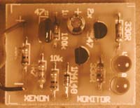
The second circuit (Xenon Monitor) is used in adjusting the speed control to your radio control gear. It enables you to view the output of the controller so that you can accurately set up Neutral and Full-speed.
Click schematic above for larger version.
(move your mouse off the screen and back again to get the enlargement arrows for large schematic)
or click HERE to download schematic as .pdf
How It Works
The FET speed controller is made up of several smaller blocks, each which
is quite easy to understand.
The R.C. transmitter sends control information to the receiver as a
string of width modulated pulses. The receiver sorts these out and sends
them to the correct servo. The electronic speed controller is connected in
place of the servo that would normally control the mechanical unit that is
usually supplied with the car. There are several things that also need to be considered in the design of
a speed control. Can the receiver and the other servo be run of the same
battery as the motor, as this will save the car carrying unnecessary weight?
What happens when this battery goes flat? What happens when the car is out
of radio range, or if the transmitter is turned off? Can the unit be run
with more than six cells? These are all things I had to address when
designing the controller, and I will explain the solutions below.
Q9 and its associated components, R20, C12 and D15 form a simple zener regulator. Voltage from the battery is fed via R20 to D15, a 5V6 zener diode which sets the reference for Q9. As Q9 is wired as an emitter follower, the voltage on its emitter will be 0.6 volts lower than its base, thus providing the receiver and servo, which are connected to the emitter, with 5 volts. This means no receiver battery pack is needed.
The decoded pulse train from the receiver is fed to the speed controller via C1. This capacitor blocks any constant logic High signal a receiver may output when first switched on or when the transmitter is switched off or out of range. This prevents the car from running away at maximum throttle. At most, the car would lurch for a second before coming to a standstill.
Under normal circumstances C1 will pass the pulse train through to R2 and C2. C2 puts a very short spike on the base of Q2, which turns it on briefly, charging C3. C3 then discharges through R5 and R6. This pulse is cleaned up and inverted to give a positive going pulse. This pulse is adjusted by R6 so it is the same length as the pulse from the receiver when the transmitter stick or trigger is in the neutral position. This pulse shall be referred to as the neutral reference pulse.
The pulse from C1 is also inverted by Q1. The inverted pulse and the neutral reference pulse are fed into an AND gate made of D4, D5, R9, IC1:C and IC1:A and a NOR gate made of D2, D3, R8 and IC1:B. When both of the pulses are the same length, the outputs of both these gates will remain at logic LOW.
When the pulse from the receiver becomes longer than the neutral reference pulse, a narrow pulse, equal to the difference in the pulse lengths is passed through to D6 and R12. This turns on Q4 briefly ensuring that C5 is discharged. (more on this later) and charges up C4 via R21. The pulse will vary in length according to the position of the transmitter stick and thus represent the speed required. Depending on the length, C4 will be charged different amounts. It then discharges more slowly through R13 and R14. The resultant ramp is fed to half of IC2, which is wired as a comparator. The 0.6 volt reference voltage being fed to the inverting input of the comparator is generated by D8, R16 and C6.
When the voltage across C4 is greater than 0.6 volts the output of the comparator will be high. R14 is adjusted so that at full throttle on the transmitter stick the voltage across C4 does not fall below 0.6v, thus giving a constant "high" out of the comparator. The output of the comparator is hence a variable mark/space ratio, continuously variable between 0 and 100%. This is the most efficient way to control a motor as very little heat is generated in the FETs as they are either fully on or fully off.
The corresponding brake circuit functions in the much the same manner except for a couple of minor differences. The first is that the AND gate passes the difference in pulse length when the incoming pulse is shorter than the neutral pulse. The second difference is that the discharge of C5 is fixed, as setting the brake is not as critical as the setting of full throttle.
Q3 and Q4 discharge the capacitor of the opposite of the circuit to the one being used to ensure that the brake FETs and the forward FETs never come on at the same time, as this would place a short circuit on the battery.
IC1:F and IC1:E along with Q5 to Q8, C8 to C10 and D11 to D13 form a small D.C. to D.C. converter. The circuit forms a tripler, but due to voltage losses in the diodes and transistors, the output is in the 16 to 18 volt range when run of a 7.2 volt battery pack. The 18 volt output of this powers IC2 which is a low power dual opamp.
To switch on a FET a voltage of 4 to 20 volts must be applied to the gate with reference to the source. The higher the voltage the more current the FET can switch. A voltage over 20 volts will destroy the FET.
The outputs of the comparator are fed to the gates of the FETs via a pair of 18 volt zener regulators. These zeners limit the voltage fed to the gates of the FETs to 18 volts and also snub any spikes over 18 volts that may be induced on the gates via the internal capacitive coupling of the gates with the load current path.
The 18 volt gate drive has two functions. It turns on the drive FETs as hard as possible, meaning less losses in the FETs and more power to the motor. It is also used to switch on the brakes. If you look at the circuit diagram you will see that the only way the brake can be switched ON is if the gates of the FETs are taken above the battery positive.
When the forward FETs are on, the current from the battery flows through the FETs to the motor. Any spikes generated are snubbed by D14, C11 and the internal reverse biased integral body diodes in the FETs themselves. Further protection is provided for IC1 by R28, D17 and C15.
When the brake FETs are ON they place a short circuit across the motor. As the motor is now functioning as a generator (the momentum of the car driving it) it will drive into the FETs which will look like an overload, forcing it to stop. The current generated by a modified class motor can be in excess of 15 amps with even greater spikes, thus in order to be able to pull the hottest motor up as quickly as possible, three FETs have been used in parallel.
Six FETs have been used in parallel for control of the motor speed. The reasons for this include being able to withstand the incredible peak pulses in excess of 200 amps, the distribution of heat between devices, eliminating the need for a heatsink in most cases and the very low ON resistance of 0.0058 ohms.
The whole circuit including the receiver and servo, when sitting in neutral, draws under 45 milliamps, which would not make any noticeable difference to the run time of the motor.
Specifications
The specifications usually given for FET speed controllers are ridiculous
even though they are half-true. What is usually not mentioned is that the
FETs would have to be at 25 degrees C for them to be true. With the amount
of current being drawn through them, it is unlikely that this would remain
the case for long. As the temperature goes up, so does the resistance of the
FETs. As the resistance goes up, so does the heat generated.
The specifications given here are for the XENON 9 speed controller when fitted with all FETs at 25 degrees C. This is so that the figures can be compared with those of other units.
| Output FETs | IRFZ42 | IRFZ40 |
| Maximum continuous current: | 276A | 306A |
| Peak current: | 870A | 960A |
| On resistance: | 0.0058R | 0.0046R |
| Input voltage: 7.2 to 8.4V | ||
Construction
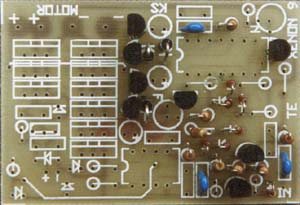
Fig.1 This diagram should be referred to when assembling the PCB. It shows the locations and value of the components. Refer to the overlay on the PCB for component orientations (shown in black here).
Depending on the use to which you are putting the XENON 9 speed controller, It is possible to build it with differing numbers of FETs. If you are only running a Mabuchi 540 motor or a similar stock motor, you will need only four FETS:- one for brakes and three for forward. For 480 and stock motors, six FETS:- one or two for brakes and four for forward. For 240 motors, drag motors and other mad motors, the six forward FETs should be fitted, with at least one for brakes.
Looking at the specifications, you may think this to be overkill, but in order to have a truly reliable and almost indestructible controller, it is necessary.
Why does the Xenon 9 allow for three brake FETS when one FET seems to be the maximum fitted to every commercial controller? It comes down to driving style. When I apply the brakes hard, I want the wheels to lock. Maybe this isn't appropriate for racing tracks, but it sure is great fun when doing stunts or just messing around.
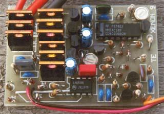
The speed controller is constructed on a printed circuit board measuring 45mm by 65mm. The board should be fiberglass to withstand the knocks it will receive during racing. The overlay on the PCB shows component location and orientation, but due to the compact nature of the layout, no component numbers or values are shown. The orientation of the FETs and the BD139 are represented by a line through the symbol on the side that metal surface or tab should face. The values are given on a separate overlay. The diodes have had their numbers shortened to fit on the diagram. 4148 refers to 1N4148 and 4002 refers to 1N4002. The location of the BC547s is shown by the letter N, and BC557s by the letter P. Zeners are represented by their zener voltage. Most other components have their value stated. C15 is soldered across D17 under the board as there is no provision for it on the top of the PCB.
Install the two links first, as these run under several components. The first runs under FETs 2 and 8. The second runs from the corner of the board to under IC2. Both links are marked on the overlay. Insulated wire must be used to stop them shorting against the pins of components. Care must be taken when inserting IC2 so that the insulation is not nicked by the pins.
Next install all of the low profile components such as IC2, the trimpots and diodes, followed by to the taller components. IC1 and the FETs are static sensitive devices and should be handled with care. Make sure that your soldering iron is properly earthed to prevent any static build up on it. It is also a good idea to earth yourself when handling the FETs, but if this is impractical, at least touch something that is earthed to discharge any static before handling them.
Install IC1, soldering pins 7 and 14 first before moving onto the others.
Insert the FETs with their tab towards the motor connections. Do not bend any of the FET leads because it will make removing the FETs very difficult, should you ever need to. It is important to make sure that the tabs of the drive FETs never come into contact with the tabs of the brake FETs. When you have all of the FETs in, run a fillet of solder along the tracks between the FETs to increase the current handling ability of the tracks.
Fig 2. These tracks must be thickened with a fillet of solder on completion of the assembly of the PCB. They will not carry the current necessary unless this is done. The short length of track running from the cathode of D14 should not be thickened, because it acts as a fuse, should a particularly bad spike short D14. If this happens, replace D14 and solder a strand of hookup wire in place of the track.
Solder in the wires to the motor and battery. The two outer holes go to the battery white the two inner holes that are marked "motor" are for the motor. In most cases a Tamiya style connector will be used. The positive wire goes to the square pin of the plug.
Solder the rainbow cable that runs to the receiver next. The brown or black wire goes to the small pad marked "-" near the 5v6 zener. The red wire goes to the pad marked "+" next to it. The orange or other colored wire goes to the other end of the PCB to the pad marked "IN". The plugs used on the receivers vary from brand to brand, as does the order in which these wires are. Plugs can be bought as spare parts usually with a length of cable included, but they can be very expensive. The plug could be cut from the servo that was being used for speed control, but doing so will disable servo. Alternately a small 3 pin 0.1 inch spaced socket can be used in most cases, one of the exceptions being the old Futaba plug.
On all the radio systems mentioned earlier, the red wire is positive, a black or brown wire is negative, and the other wire, be it white, blue or orange, is the signal wire.
If you are unsure, open the receiver and trace the wires from the receiver's battery to the PCB.
Receivers having an internal battery eliminator (B.E.C.) no longer require the separate wires to their power input because they, like normal receivers will be powered by the B.E.C. in the speed controller.
Fig 3. This diagram shows the external wiring of the XENON 9 speed controller. Take care with the polarity of the battery connector, as a reverse connection will destroy the unit. This diagram shows a Tamiya standard connector, which is the most common in use, however some brands use the same connectors wired in different ways. Check this before connecting the battery. Refer to the text when connecting the receiver plug. Almost every brand is different!
Heatsinks are not necessary for most applications, because most likely it will not be run for more than fifteen minutes at a time (the limit of a 1200mAh pack on a Mabuchi motor) but if you are putting the speed controller to heavier use in a boat or a similar application where larger batteries are carried, a small heatsink may become necessary. DO NOT UNDER ANY CIRCUMSTANCES BOLT THE BRAKE FETS AND THE DRIVE FETS TO THE SAME HEATSINK, AS THIS WILL APPLY THE BRAKES PERMANENTLY, DESTROYING THE DRIVE FETS THE FIRST TIME YOU POWER UP. The brake FETs will never get hot enough to need heatsinking. It may be appropriate to use fully insulated FETs for the brakes, as shorting them to the drive FETs will then be impossible.
Important
FETs have a diode equal to the current handling of the FET that runs between the source and drain. If you reverse the battery connections to the speed controller, the battery will be shorted through these diodes in both the brake and drive FETs, causing excessive currents to flow through the FETs, destroying them.
It is also very important to make sure that your motor has the radio interference capacitors between the brushes and the can of the motor. A 100n can be added between the brushes for added reduction of sparking at the commutator.
Avoid disconnecting the battery when the motor is running as this removes the protection of the low impedance of the battery, allowing the motor to introduce some sizable spikes into the Xenon.
Testing and Adjusting the Xenon
 In order to set up the XENON 9 speed controller properly, it is necessary to
monitor the output of the controller. The XENON MONITOR is a small logic
probe designed for this purpose. It is constructed on a separate small
printed circuit board and is connected to the output of the XENON 9 speed
controller with alligator clips. There are two LEDs on the monitor. The
green one that indicates drive and the red one which comes on when full
throttle is reached.
In order to set up the XENON 9 speed controller properly, it is necessary to
monitor the output of the controller. The XENON MONITOR is a small logic
probe designed for this purpose. It is constructed on a separate small
printed circuit board and is connected to the output of the XENON 9 speed
controller with alligator clips. There are two LEDs on the monitor. The
green one that indicates drive and the red one which comes on when full
throttle is reached.
It works as follows. When the XENON 9 is in neutral or has the brakes on, there is no voltage across the output terminals, so the XENON monitor will be off, but as soon as some drive pulses are present, they will turn on LED 2. The amount of drive can be estimated by the brightness of the LED. The rest of the circuit is to detect when the power is on constantly (100% drive). Every time a pulse appears on the input of the monitor, C13 passes it, turning on Q10. This charges C14. Q11 is running as an emitter follower, so when C14 is charged, Q11 is held low and LED 1 cannot light. C14 discharges through R25, but if another pulse comes, C14 is "topped up" again preventing LED 1 from illuminating. When full throttle is reached, there are no pulses being fed to the monitor, just a D.C. voltage. C13 blocks the D.C. preventing Q10 from charging C14. R25 discharges C14, pulling Q11 up to rail voltage, lighting LED 1.
Connect the XENON 9 to your radio gear and switch on the transmitter. Center the throttle trim. Making sure that you have the polarity correct, connect the XENON MONITOR to the XENON 9. Connect the XENON 9 to a 7.2 volt ni-cad pack via a 10 ohm resistor. This resistor will prevent the FETs from destroying themselves, should you have made a construction error.
Adjust R6, which is marked by an "N" on the PCB, so that the green LED comes on, then back off until it just stops. This sets your neutral so that release of the stick or trigger, when driving, will allow your car to free-wheel. Now move the trigger or stick to about 7/8ths of travel and adjust R14 (marked "F" on the PCB) until the red LED comes on. This sets the full throttle position. If the green LED comes on when you move the stick or trigger in the reverse direction, you will need to change the servo reverse switch on your transmitter or reverse the joystick assembly. Pushing the joystick UP is the standard direction for forward. If the LEDs do not light, or stay lit the whole time, go back and check the construction and wiring. If the Neutral pot has an effect, but you are not able to get the green LED to go out, increase the value of R5 to 47k. This will only be necessary if the transmitter pulses are exceptionally long. Alternately if they are exceptionally short, reduce the value of R5 to about 10k.
Using the Xenon
D14 is A 33v zener. This is to protect the FETs from damage by a spike greater than 50V. Occasionally a motor will generate a really big spike. This will destroy D14 and blow a short length of fusible track (see Fig.2). Replace the zener and solder a strand of wire across the blown track if this happens. The only time I've seen this happen was when a friend took the prototype to a speedway race, and was using something like a 10 turn quad motor. He had also managed to soak the controller in an off-track excursion.
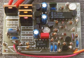
The complete 9-FET version
When you have finished assembling and testing the unit, it should be shrink wrapped to keep out the dirt and mud. Two pieces of lexan or plastic should be cut, the first being the size of the PCB, the second just big enough to cover the tops of all of the FETs. The first goes under the PCB to prevent the component pins from puncturing the heatshrink tubing. The second covers the top of the FETs to prevent them cutting through the heatshrink tubing, should they get hot. Clear tubing should be used, as it will allow you to see where you need to put two small holes to get to the trimpots.
The XENON 9 speed controller can now be mounted in your buggy or car. It helps to have some airflow around the unit, but is much more important to make sure it does not get wet or muddy. If it does, wash it under clean hot running water as soon as you can, then dry it with a hair-drier. The trimpots may become unreliable if you have to do this, so if they do, replace them.
Speed boat owners can leave off the brake FETs, as these will be of little use. Instead, a large Schottky diode should be connected there in reverse bias, to replace the ones from the FETs, otherwise, the unit can be constructed in much the same manner with particular attention paid to making the unit watertight.
The Xenon has several advantages over other speed controllers, but the greatest is that in the unlikely event it is damaged, you can fix it yourself, saving yourself the cost of another unit or the outrageous repair charges that are often close to the replacement value of the unit.
Fig 4. The symbol and pinout of the IRFZ40 and IRFZ42.
Note
the internal diode has been shown in the symbol.
Parts list
This is a guide only. Parts needed will vary with individual
constructor's needs. The kit may not include these exact parts.
For example, BUZ11 may be substituted for the FETs. Battery connectors will
not be included.
| |
|
Article, art & circuit design by Ken Stone. Originally published in "Dirt & Track Magazine" issue 10.