|
Prototyping Boards |
Working with
Prototyping Boards
Boards are available from
Talking
Electronics.
![]()
It doesn't matter if you are designing a new
microcontroller project or a simple transistor amplifier, the first
necessity of designing a project is the ease of
changing components.
If you think a project will work without testing, modifying and
altering things, you are kidding yourself.
It sometimes takes hundreds of changes to get a project working
perfectly.
And if the components are not easy to change, you may be reluctant to do
the finer adjusting.
That's why a prototyping board must be designed for easy access and must
be universal, so that all types of components can be fitted.
Here are 4 prototyping boards from Talking Electronics:
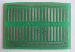
Matrix Board MkIII
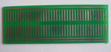
Matrix Board MkIV
Prototyping boards are not designed to look aesthetic. They are designed
to be functional and reduce frustration.
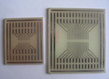
Two surface-mount boards from
the range from Talking Electronics
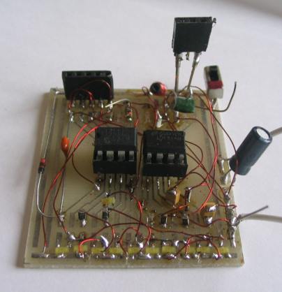
A prototype project is sometimes called a "rats-nest" or "birds-nest."
There are two levels of prototyping.
The first level requires no experimenting. It's simply building a
"proven" circuit on a board and connecting it to other items.
The second level involves experimenting and changing component values.
For this, the components should be on one side of the board.
The end-result is a jumble but it's the only way to be able to get
to everything:
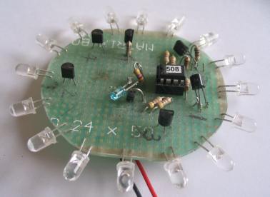
11 LEDs and surface-mount components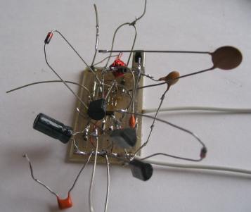
design and before the final board
Many prototyping boards on the market are quite useless. They are not
really prototyping boards but rather "Universal Boards" that will accept
different components and hand wiring.
Using a Matrix Board for designing
The essential part of a prototyping board is the accessibility of each
and every component so that voltage and waveforms can be measured.
But the most important reason is each component must be easily removed
and/or replaced. That's why soldering components though holes is not
suitable. Sometimes a component has to be changed 4 or 5 times. Imagine
the difficulty of pulling out a component every time you want to alter
the value.
Some of our prototype boards have certainly become over-crowded but
that's how a circuit gets designed.
Initially you think the circuit will need a few components and choose a
small PC board. It quickly gets over-crowded but as the circuit
develops, you can easily see what each component is doing and it's
really not complex at all.
You will notice many of the circuits in the photos above have been
designed with surface-mount components.
These are just as cheap as normal components and since they take up less
space on the board, it creates less clutter and you can see what you are
doing.
Surface-mount
kits are available from Talking Electronics and when combined with
the prototyping boards, you will be able to develop circuits that are
very compact.
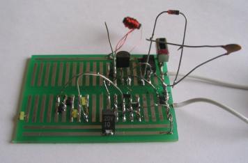
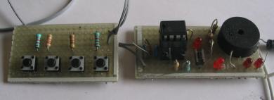
The second step before making a PC board is to lay out the components on
a matrix board in the same locations as they will appear in the final
design.
This will give you two answers. It will let you know if the project will
work and give you some idea of the size of the board and where each item
is positioned. The underside of the board is generally a mass of fine
wiring and it may need one more layout to produce wiring that does not
cross at any location. Any wires that cross each other need a jumper and
by carefully re-laying the board, no jumpers will be needed. Here is our
example of the PIC Lab-1 before the final PC layout. The stage before
this was a "rats-nest" and the final design you can see in the PIC Lab-1
article.
If you think our projects "magically appear from no-where" you should
see our boxes of thousands of prototypes!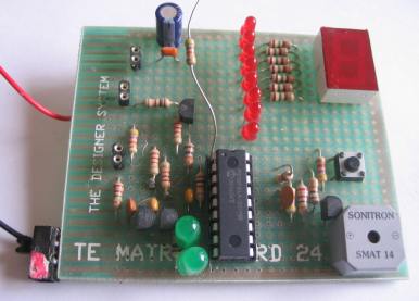
The second step to making a PC
board
2/11/07