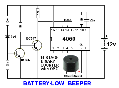
This circuit will produce a beep-beep-beep from the piezo buzzer when the
battery voltage falls to about 10v.
This is very handy when you have a battery powering a piece of
equipment and you don't know its state of charge.

When the voltage is above 10v, the zener diode conducts and turns ON
the first transistor. The voltage between the collector and emitter
of this transistor is less than 0.3v and the voltage on the base of
the second transistor is 0.3v. Thus the second transistor is not
turned ON and it is effectively removed from the circuit. This means
the reset pin of the CD 4060 is connected to the positive rail via a
1M resistor. This puts a HIGH on the reset pin and turns the chip
off and prevents the oscillator producing clock pulses.
The chip contains inverters between pins 9, 10 and 11 so that when
components are connected to these pins, an oscillator is produced.
The technical name for this oscillator is called a CLOCK.
When pin 12 is taken HIGH it inhibits the oscillator (prevents the
clock pulses passing to the divider stages).
When the battery voltage falls below 10v, the first transistor
is turned OFF and the second transistor is turned ON. This takes the
reset line to the 0v rail and the chip allows the clock pulses from
the oscillator to pass to a set of flip flops arranged to divide the
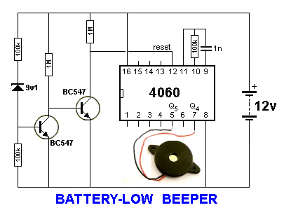
signal. Pin 7 divides the signal by 16 to produce a beep-beep-beep
from the piezo buzzer. The buzzer normally produces a constant tone
but output pin 7 goes HIGH/LOW at about one cycle per second and
this turns the buzzer ON and OFF to produce a clearer alert signal.
The circuit takes 30uA when "sitting around" and less than 1mA when
producing a beep.
If you do not have a piezo buzzer, a piezo diaphragm can be used.
The output volume will not be as loud. The oscillator components
will need to be changed to produce a higher clock frequency.
This frequency will be divided-down and detected at one or two of
the outputs. You can try all the outputs to see what result is the
best.

If you do not have a 9v1 zener, it can
be made from 5v6 zener and 3v6 zener or a 5v6 and a white LED or two
red LEDs.
It can also be made from three white LEDs and a red LED.
You can use a zener, LEDs and a signal diode to adjust the voltage
to any desired value.
When a very small current flows though a zener, LED or diode, the
characteristic voltage that develops across it is LESS than when its
rated current flows. However this lower voltage can be used to
produce a "trigger-point." The only way to determine this voltage is
to add the component to the circuit.
The first transistor reacts at this trigger-point and the second
transistor simply inverts the voltage on the collector.
The second transistor is not classified as an amplifier but an
INVERTER.
BATTERY-LOW BEEPER
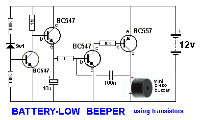
USING TRANSISTORS
If you want a simpler circuit using transistors, the following
design will produce a constant beep when the battery voltage falls below
10v.
The actual voltage can be adjusted by using LEDs and diodes in place of the
zener.

The mini piezo buzzer contains a transistor and inductor to produce a high
amplitude oscillator to drive the diaphragm and produce a loud squeal from a
supply of 5v to about 10v. It will not "turn on" from a slowly rising
voltage so the circuit must be designed to rise rapidly when the voltage
drop down to the "detection-point."
That's the purpose of the 3rd and 4th transistors. They form a high-gain
amplifier where the output rises quickly due to the positive feedback
provided by the 100n.
As soon as the third transistor starts to turn on, it turns on the 4th
transistor and the collector voltage rises. The right-plate of the 100n
rises and since the 100n is uncharged, the left plate (lead) rises and
increases the voltage and also the current into the base of the third
transistor. This makes it turn on more and the action continues very quickly
until both transistors are fully turned on. They stay turned on by the
voltage (and current) provided by the first transistor.
Even though we normally see these two transistors used as an oscillator, we
can use the "rapid turn-on" feature to "kick-start" the piezo and if the
third transistor is provided with too-much voltage (current) on the base,
the oscillator feature will not occur because the current into the base is
too high and the 100n cannot remove this current during the turn-off period
of the cycle. The only unusual feature of this circuit is the oscillator
section starts to oscillate at very low amplitude when the second transistor
turns off (when the battery voltage rises) and a 10u has been added to stop
this oscillation so it takes no current when the buzzer is not producing a
tone. The
only stages that take any quiescent current are the zener and the 1M
collector load resistor.
ooo00000oooo
3-7-2013
|


