Clap Switch


This circuit will turn ON a LED when it detects a sound and the LED will turn OFF when it detects the next sound.

The Circuit

The circuit consists of 4 transistors and an electret microphone.
The first transistor is turned on very slightly via the 470k resistor on the base and this creates a voltage of about 0.2v between the collector-emitter terminals.
This voltage is below 0.6v needed to turn on the second transistor and the second transistor is not turned on and the collector voltage is equal to about rail voltage.
The signal from the electret mic consists of positive and negative waveforms and it is the negative portion of the waveform that reduces the voltage on the base of the first transistor to turn it OFF slightly. This raises the voltage on the collector and the second transistor is turned ON. The voltage on the collector drops and this drop is passed to the positive lead of the 1u electrolytic.
The negative lead of the 1u also drops and this fall is passed to the 47k resistor. The other lead of the 47k is connected to the base of the first transistor and has the effect of turning it OFF more.
This action continues around the two transistors until the first transistor is fully turned OFF and the second transistor is full ON.  This action is called REGENERATION and occurs without any further input from the microphone.
The output from the second transistor goes to the next section consisting of two transistors in a bi-stable arrangement. In other words, they will sit with the first ON and second OFF or vise versa.
There is no way to tell how they will sit when the power is applied. One transistor will come on faster than the other and that's they was they will sit.
Suppose the third transistor is ON and the fourth is OFF.
The signal from the second transistor moves from a high value to a low value when the first two transistors activate into the regenerative state.
The fourth transistor has zero volts on the base and reducing this voltage via the pulse from the second transistor will have no effect.
However the third transistor has 0.6v o the base and reducing this voltage will cause the transistor to change states.
That's how the LED turns ON or OFF.
After a short period of time the LOW on the base of the first transistor gradually rises because the 470k charges the 1u via the 47k and the first transistor starts to turn ON.
This action robs the second transistor of base voltage and it turns OFF. Both leads of the 1u electrolytic rise and this delivers a higher current to the base of the first transistor to turn it ON fully.
The first two transistors have now changed state and wait for the next signal from the electret microphone.


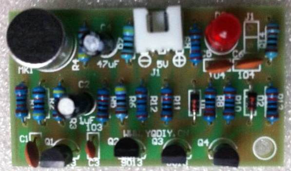
The photo identifies all the components and how to fit them to the printed circuit board. You will have to refer to the circuit to determine the value of each resistor. Use a multimeter to measure the value of each resistor before fitting it or use the photo below to check the value of each resistor:


The colours for each resistor


Use a constant-heat soldering iron (320 degrees C) and fine solder (0.8mm).
Fit one component and splay the legs slightly so it doesn't fall out of the holes. Turn the board over and hold the soldering iron on one side of the lead and the solder on the other side. The solder will melt and flow across to the iron. This will take less than one second.
Snip the leads close to the solder-joint. Solder one component at a time. Use the photo below to identify each component and how it is fitted to the board. All the components must be fitted around the correct way and there is only one way to fit them. The resistors can be connected either-way-around as they are not a polarized component.
The electret microphone has one lead connected to the case. This goes to the 0v rail.


You can buy this kit for about $4.00 post-free

22-7-2013