|
FLIP FLOP |
|
This circuit is commonly called a Flashing LED or Blinking LED and has the technical name FLIP FLOP or ASTABLE MULTIVIBRATOR. It uses two transistors to alternately flash two LEDs and will operate from 3v to 9v. Principle of Operation There will be a slight difference between the gain (the ability to amplify) of the two transistors, Q1 and Q2 and one of them will turn on faster to start the circuit flashing. If Q1 turns on first, the voltage on the collector will be very near to 0v and D1 will illuminate. At the same time the positive lead of C1 will be at about 0v and the negative lead will also be about 0v. This will put 0v on the base of Q2 and Q2 will be turned off. This means LED D2 will not be illuminated. C1 will gradually charge (in the opposite direction to its polarity) via 10k resistor R2 and when the base of Q2 see a voltage of about 0.65v, it will start to turn ON. This will reduce the voltage on the collector of Q2 and make the positive lead of C2 drop. This will cause the negative lead of C2 to drop also and reduce the voltage on the base of Q1. This will start to turn off Q1 and the voltage on the collector will rise. This will further increase the voltage on the base of Q2 and it will turn on more. This action is called REGENERATIVE ACTION as one transistor will turn off and cause the other to turn on. This occurs very quickly and the two transistors swap states. This means the second LED illuminates and the first LED is not illuminated. The flashing frequency depends on the
value of C1, C2, R2 and R3.
Circuit
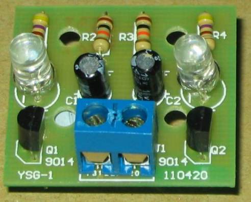
The photo identifies all the components and
how to fit them to the printed circuit board.
The photo above
shows all the components fitted to the board. You can see the
flat on the side of the LED and the placement of the two electrolytics. The
two 10k resistors are in the centre and the two 470 ohm resistors are at the
edges of the board. You can buy this kit for about $2.00 post-free
13-6-2013 |