|
HEART FLASHER |
|
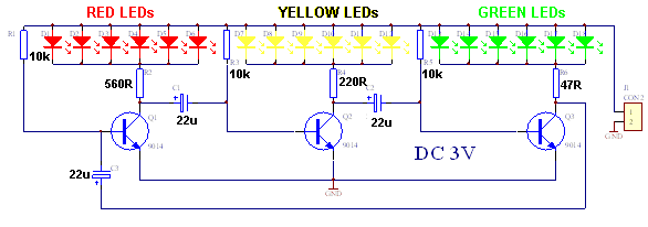
This circuit is commonly called a RING-OF-THREE as it has three timing (or delay) sections to produce an oscillator. It uses three transistors to alternately flash three sets of coloured LEDs and will operate from 3v to 9v. Two sets of LEDs are illuminated at any time and the third set is OFF. Principle of Operation The circuit consists of three identical amplifier stages consisting of a transistor. Each stage is connected via a capacitor called an electrolytic. This is a capacitor with a high capacitance. Connected to the electrolytic is a 10k resistor. The reason why the circuit oscillates or "flashes" is due to a state called instability. The circuit is unstable. It is very difficult to describe this circuit because it is UNSTABLE and there is no starting-point. Let's start with the first transistor at the point where the circuit is first turned ON. The circuit needs this turn-on pulse to start the "oscillation." Suppose the first transistor is not turned ON. The second transistor will be turned ON via the 22u on its base being charged via the 560R and through the red LEDs. This will turn on the yellow LEDs and the third transistor will be turned OFF because the 22u on its base is uncharged. The Circuit
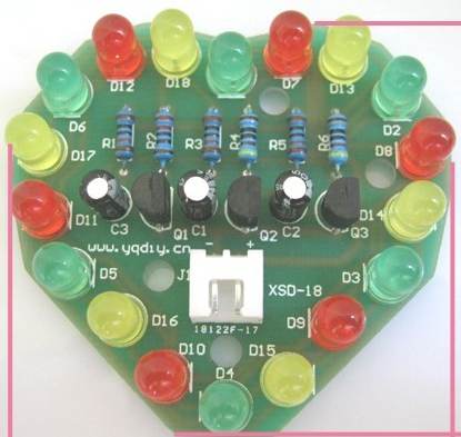
The photo identifies all the components and
how to fit them to the printed circuit board.
The photo above
shows all the components fitted to the board. You can see the
flat on the side of the LED and the placement of the two electrolytics. The
two 10k resistors are in the centre and the two 470 ohm resistors are at the
edges of the board. You can buy this kit for about $2.00 post-free
21-7-2013 |